CYLINDER HEAD INSPECTION

PROCEDURE
-
INSPECT CYLINDER HEAD FOR FLATNESS
-
Using a precision straightedge and feeler gauge, measure the warpage of the contact surfaces where the cylinder head sub-assembly contacts the cylinder block and manifold.
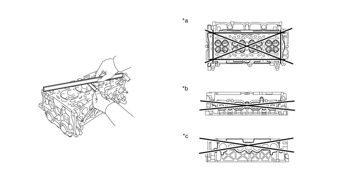
Text in Illustration *a Cylinder Block Side *b Intake Manifold Side *c Exhaust Manifold Side Maximum warpage Surface Specified Condition Cylinder block side 0.05 mm (0.00197 in.) Intake manifold side 0.10 mm (0.00394 in.) Exhaust manifold side 0.10 mm (0.00394 in.) If the warpage is greater than the maximum, replace the cylinder head sub-assembly.
-
-
INSPECT CYLINDER HEAD FOR CRACKS
-
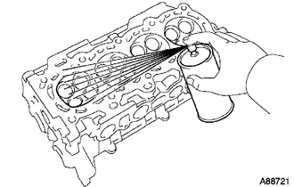
Using a dye penetrant, check the intake ports, exhaust ports and cylinder head sub-assembly surface for cracks.
If cracked, replace the cylinder head sub-assembly.
-
-
INSPECT INTAKE VALVE
-
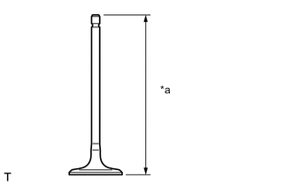
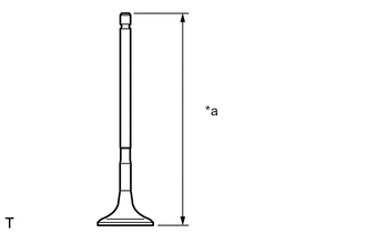
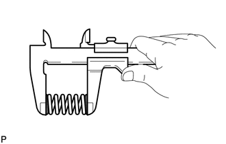
Text in Illustration *a Overall Length Using a vernier caliper, measure the overall length of the intake valve.
Standard overall length 89.25 mm (3.51 in.) Minimum overall length 88.95 mm (3.50 in.) If the overall length is less than the minimum, replace the intake valve.
-
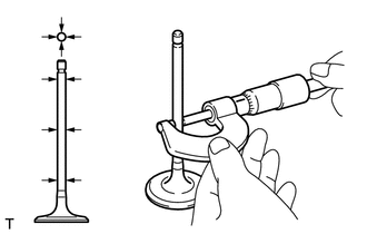
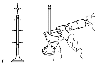
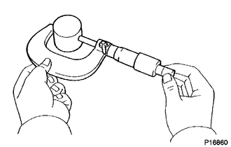
Using a micrometer, measure the diameter of the valve stem.
Standard valve stem diameter 4.970 to 4.985 mm (0.19567 to 0.19626 in.) If the valve stem diameter is not as specified, check the oil clearance.
-
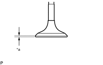
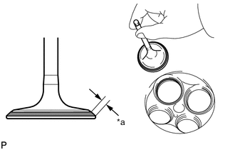
Text in Illustration *a Margin Thickness Using a vernier caliper, measure the valve head margin thickness.
Standard margin thickness 1.0 mm (0.0394 in.) Minimum margin thickness 0.7 mm (0.0276 in.) If the margin thickness is less than the minimum, replace the intake valve.
-
-
INSPECT EXHAUST VALVE
-
Text in Illustration *a Overall Length Using a vernier caliper, measure the overall length of the exhaust valve.
Standard overall length 87.90 mm (3.46 in.) Minimum overall length 87.60 mm (3.45 in.) If the overall length is less than the minimum, replace the exhaust valve.
-
Using a micrometer, measure the diameter of the valve stem.
Standard valve stem diameter 4.965 to 4.980 mm (0.19547 to 0.19606 in.) If the valve stem diameter is not as specified, check the oil clearance.
-
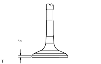
Text in Illustration *a Margin Thickness Using a vernier caliper, measure the valve head margin thickness.
Standard margin thickness 1.15 mm (0.0453 in.) Minimum margin thickness 0.85 mm (0.0335 in.) If the margin thickness is less than the minimum, replace the exhaust valve.
-
-
INSPECT COMPRESSION SPRING
-
Using a vernier caliper, measure the free length of the compression spring.
Standard free length 59.77 mm (2.35 in.) -
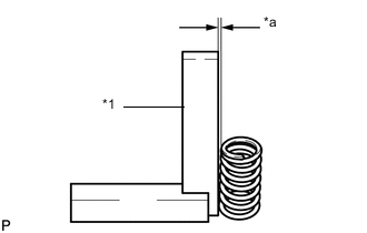
Text in Illustration *1 Steel Square *a Deviation Using a steel square, measure the deviation of the compression spring.
Maximum deviation 1.6 mm (0.0630 in.)
-
-
INSPECT VALVE GUIDE BUSH OIL CLEARANCE
-
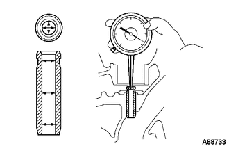
Using a caliper gauge, measure the inside diameter of the valve guide bush.
Bush inside diameter 5.01 to 5.03 mm (0.197 to 0.198 in.) -
Subtract the valve stem diameter measurement from the valve guide bush inside diameter measurement.
Standard oil clearance Valve Guide Bush Specified Condition Intake 0.025 to 0.060 mm (0.000984 to 0.00236 in.) Exhaust 0.030 to 0.065 mm (0.00118 to 0.00256 in.) Maximum oil clearance Guide Bush Specified Condition Intake 0.08 mm (0.00315 in.) Exhaust 0.10 mm (0.00394 in.) If the oil clearance is greater than the maximum, replace the valve and valve guide bush Click here.
-
-
INSPECT VALVE SEATS
-
Apply a light coat of Prussian blue to the valve face.
-
Lightly press the valve face against the valve seat.
-
Text in Illustration *a Width Check the valve face and seat according to the following procedure.
-
If Prussian blue appears 360° around the valve face, the valve face is concentric. If not, replace the valve.
-
If Prussian blue appears 360° around the valve seat, the guide and valve face are concentric. If not, resurface the valve seat.
-
Check that the valve seat contact is in the middle of the valve face with the valve seat width between 1.0 and 1.4 mm (0.0394 to 0.0551 in.).
-
-
-
INSPECT VALVE LIFTER
-
Using a micrometer, measure the valve lifter diameter.
Standard lifter diameter 30.966 to 30.976 mm (1.2191 to 1.2195 in.)
-
-
INSPECT VALVE LIFTER OIL CLEARANCE
-
Using a caliper gauge, measure the valve lifter bore diameter of the cylinder head sub-assembly.
Standard lifter bore diameter 31.009 to 31.025 mm (1.2208 to 1.2215 in.) -
Subtract the lifter diameter measurement from the lifter bore diameter measurement.
Standard oil clearance 0.033 to 0.059 mm (0.00130 to 0.00232 in.) Maximum oil clearance 0.1 mm (0.00394 in.) If the oil clearance is greater than the maximum, replace the valve lifter. If necessary, replace the cylinder head sub-assembly.
-
-
INSPECT CAMSHAFT
-
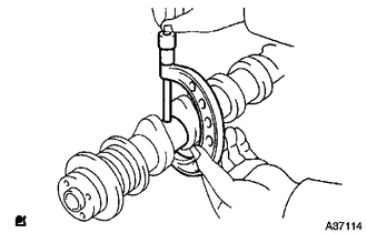
Inspect the camshaft for runout.
-
Place the camshaft on V-blocks.
-
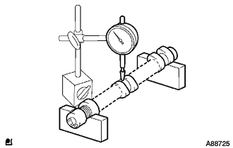
Using a dial indicator, measure the circle runout at the center journal.
Maximum circle runout 0.03 mm (0.00118 in.) If the circle runout is greater than the maximum, replace the camshaft.
-
-
Inspect the cam lobes.
-
Using a micrometer, measure the cam lobe height.
Standard cam lobe height 42.261 to 42.461 mm (1.6638 to 1.6717 in.) Minimum cam lobe height 42.16 mm (1.6598 in.) If the cam lobe height is less than the minimum, replace the camshaft.
-
-
Inspect the camshaft journals.
-
Using a micrometer, measure the journal diameter.
Standard journal diameter Journal Specified Condition No. 1 journal 34.449 to 34.465 mm (1.3563 to 1.3569 in.) Other journals 22.949 to 22.965 mm (0.90350 to 0.90413 in.) If the journal diameter is not as specified, check the oil clearance.
-
-
-
INSPECT NO. 2 CAMSHAFT
-
Inspect the camshaft for runout.
-
Place the camshaft on V-blocks.
-
Using a dial indicator, measure the circle runout at the center journal.
Maximum circle runout 0.03 mm (0.00118 in.) If the circle runout is greater than the maximum, replace the No. 2 camshaft.
-
-
Inspect the cam lobes.
-
Using a micrometer, measure the cam lobe height.
Standard cam lobe height 44.046 to 44.146 (1.7341 to 1.7380 in.) Minimum cam lobe height 43.90 mm (1.7283 in.) If the cam lobe height is less than the minimum, replace the No. 2 camshaft.
-
-
Inspect the camshaft journals.
-
Using a micrometer, measure the journal diameter.
Standard journal diameter Journal Specified Condition No. 1 journal 34.449 to 34.465 mm (1.3563 to 1.3569 in.) Other journals 22.949 to 22.965 mm (0.90350 to 0.90413 in.) If the journal diameter is not as specified, check the oil clearance.
-
-
-
INSPECT CAMSHAFT THRUST CLEARANCE
-
Install the camshafts Click here.
-
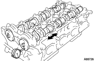
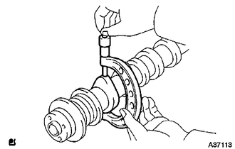
Using a dial indicator, measure the thrust clearance while moving the camshaft back and forth.
Standard thrust clearance 0.040 to 0.095 mm (0.00157 to 0.00374 in.) Maximum thrust clearance 0.11 mm (0.00433 in.) If the thrust clearance is greater than the maximum, replace the camshaft. If necessary, replace the camshaft bearing caps and the cylinder head sub-assembly.
-
-
INSPECT CAMSHAFT OIL CLEARANCE
Note
Do not turn the camshafts.
-
Clean the camshaft bearing caps and the camshaft journals.
-
Place the camshafts on the cylinder head sub-assembly.
-
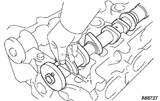
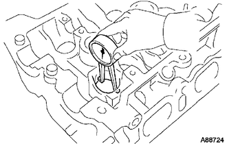
Text in Illustration *1 Plastigage Lay a strip of Plastigage across each of the camshaft journals.
-
Install the camshaft bearing caps Click here.
-
Remove the camshaft bearing caps Click here.
-
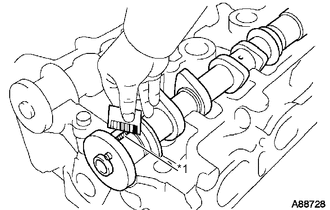
Text in Illustration *1 Plastigage Measure the Plastigage at its widest point.
Standard oil clearance 0.035 to 0.072 mm (0.00138 to 0.00283 in.) Maximum oil clearance 0.115 mm (0.00453 in.) If the oil clearance is greater than the maximum, replace the camshaft. If necessary, replace the camshaft bearing caps and the cylinder head sub-assembly.
Note
Completely remove the Plastigage.
-