CYLINDER HEAD GASKET INSTALLATION
CAUTION / NOTICE / HINT
Tech Tips
Perform "Inspection After Repairs" after replacing the cylinder head sub-assembly Click here.
PROCEDURE
-
INSPECT CYLINDER HEAD SET BOLT
-
INSTALL CYLINDER HEAD GASKET
-
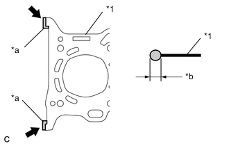
Text in Illustration *1 Cylinder Head Gasket *a Apply Seal Packing To The Inner Corners *b 4.5 to 5.5 mm (0.177 to 0.217 in.) 
Seal Packing Black Apply seal packing to a new cylinder head gasket as shown in the illustration.
Seal packing Toyota Genuine Seal Packing Black, Three Bond 1207B or equivalent Note
Install the cylinder head sub-assembly within 3 minutes and tighten the cylinder head bolts within 15 minutes after applying seal packing.
-
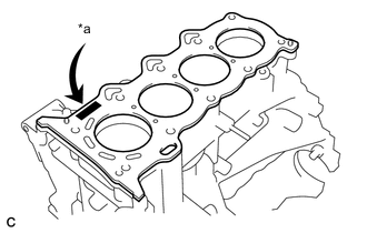
Text in Illustration *a Lot Number Place the cylinder head gasket on the cylinder block with the Lot No. facing upward.
Note
-
Remove any oil from the contact surface.
-
Be careful of the installation direction.
-
-
-
INSTALL CYLINDER HEAD SUB-ASSEMBLY
Tech Tips
-
Perform "Inspection After Repairs" after replacing the cylinder head sub-assembly Click here.
-
The cylinder head bolts are tightened in 2 progressive steps.
-
Place the cylinder head sub-assembly on the cylinder block.
Note
-
Ensure that no oil is on the mounting surface of the cylinder head sub-assembly.
-
Place the cylinder head sub-assembly gently in order not to damage the cylinder head gasket.
-
-
Apply a light coat of engine oil to the threads and under the heads of the 10 cylinder head bolts.
Note
Ensure that no engine oil drips from any of the cylinder head bolts.
-
Step 1:
-
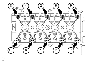
Using several steps, uniformly install and tighten the 10 cylinder head bolts and 10 washers with an 8 mm bi-hexagon wrench in the order shown in the illustration.
- Torque:
- 29 N*m { 300 kgf*cm, 22 ft.*lbf }
-
-
Step 2:
-
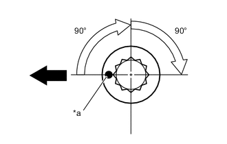
Text in Illustration *a Paint Mark 
Engine Front Mark each cylinder head bolt head with paint as shown in the illustration.
-
Further tighten the cylinder head bolts 90°, and then an additional 90° as shown in the illustration.
-
-
Check that the paint mark is now at a 180° angle to the front.
-
After tightening the cylinder head bolts, wipe off the seal packing material that seeped out from the contact surface between the cylinder head sub-assembly and cylinder block.
-
-
INSTALL CAMSHAFT
-
Apply a light coat of engine oil to the camshaft and cylinder head sub-assembly journals.
-
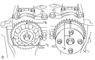
Text in Illustration *a Timing Mark *b Timing Mark (Rectangle) *c Mark (Circle) Place the camshaft and No. 2 camshaft on the cylinder head sub-assembly with the timing mark on the camshaft timing gear assembly and camshaft timing sprocket facing upward.
Tech Tips
There are 3 marks on the camshaft timing sprocket. Make sure that the timing mark (rectangle) is at the top.
-
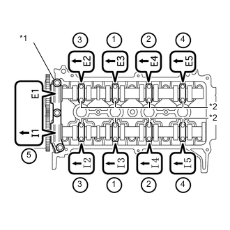
Text in Illustration *1 No. 1 Camshaft Bearing Cap *2 No. 2 Camshaft Bearing Cap Check the front marks and numbers on the No. 1 camshaft bearing cap and 8 No. 2 camshaft bearing caps, then temporarily install them with the 19 bolts.
-
Uniformly tighten the 19 bolts in the sequence shown in the illustration.
- Torque:
- No. 2 camshaft bearing cap
- 13 N*m { 129 kgf*cm, 9 ft.*lbf }
- No. 1 camshaft bearing cap
- 23 N*m { 234 kgf*cm, 17 ft.*lbf }
Note
Uniformly tighten the bolts while keeping the camshaft level.
-
-
INSTALL CHAIN SUB-ASSEMBLY
-
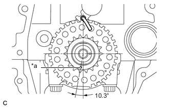
Text in Illustration *a Timing Mark Set the crankshaft in the position shown in the illustration.
Tech Tips
The crankshaft will be set to 90° ATDC and the timing mark will be at the location shown in the illustration.
-
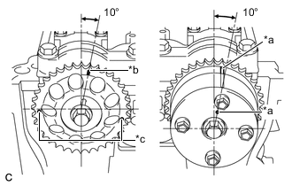
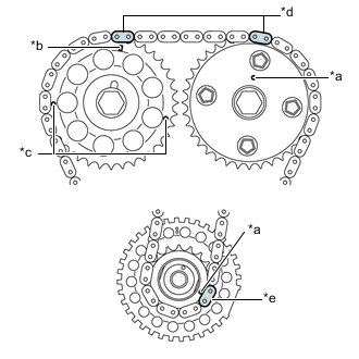
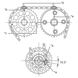
Text in Illustration *a Timing Mark *b Timing Mark (Rectangle) *c Mark (Circle) Set the camshaft timing gear assembly and camshaft timing sprocket in the positions shown in the illustration.
Tech Tips
There are 3 marks on the camshaft timing sprocket. Make sure to set the timing mark (rectangle) to 10° as shown in the illustration. Make sure to set the camshaft timing gear assembly to 10° as shown in the illustration. This is the location of the camshafts when the crankshaft is 20° ATDC.
-
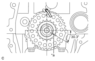
Text in Illustration *a Timing Mark Set the crankshaft in the position shown in the illustration.
Tech Tips
The crankshaft will be set to 20° ATDC and the timing mark will be at the location shown in the illustration.
-
Install the No. 1 chain vibration damper with the 2 bolts.
- Torque:
- 9.0 N*m { 92 kgf*cm, 80 in.*lbf }
-
Text in Illustration *a Timing Mark *b Timing Mark (Rectangle) *c Mark (Circle) *d Orange Mark Plate *e Yellow Mark Plate Align the timing marks of the camshaft and crankshaft with the mark plates of the timing chain sub-assembly and install the timing chain sub-assembly.
Tech Tips
-
To prevent the No. 2 camshaft from springing back, turn it using a wrench and set it at the mark on the chain.
-
There are 3 marks on the camshaft timing sprocket. Make sure to align the mark plate with the timing mark (rectangle).
-
-
Install the chain tensioner slipper.
-
Install the No. 1 chain tensioner assembly with the 2 bolts.
- Torque:
- 9.0 N*m { 92 kgf*cm, 80 in.*lbf }
-
Remove the hexagon wrench from the No. 1 chain tensioner assembly.
-
Text in Illustration *a Timing Mark *b Timing Mark (Rectangle) *c Mark (Circle) *d Orange Mark Plate *e Yellow Mark Plate Turn the crankshaft approximately 20° counterclockwise to set it to TDC. Make sure that the timing marks and mark plates are correctly positioned.
Tech Tips
There are 3 marks on the camshaft timing sprocket. Make sure that the timing mark (rectangle) is at the top.
-
-
INSTALL EXHAUST MANIFOLD
-
INSTALL MANIFOLD SUPPORT BRACKET
-
INSTALL NO. 1 EXHAUST MANIFOLD HEAT INSULATOR
-
INSTALL INTAKE MANIFOLD
-
INSTALL INTAKE MANIFOLD STAY
-
INSTALL TIMING CHAIN COVER