CYLINDER HEAD GASKET REMOVAL
PROCEDURE
-
REMOVE TIMING CHAIN COVER
-
REMOVE INTAKE MANIFOLD STAY
-
REMOVE INTAKE MANIFOLD
-
REMOVE NO. 1 EXHAUST MANIFOLD HEAT INSULATOR
-
REMOVE MANIFOLD SUPPORT BRACKET
-
REMOVE EXHAUST MANIFOLD
-
REMOVE NO. 1 CHAIN TENSIONER ASSEMBLY
-
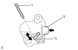
Text in Illustration *1 Hexagon Wrench *2 Plunger *3 Stopper Plate Turn the stopper plate of the No. 1 chain tensioner assembly clockwise and push in the plunger with the lock released.
-
Turn the stopper plate of the No. 1 chain tensioner assembly counterclockwise and insert a hexagon wrench into the hole in the stopper plate to lock with the plunger pushed in.
-
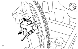
Remove the 2 bolts and No. 1 chain tensioner assembly.
Note
Do not rotate the crankshaft with the No. 1 chain tensioner removed.
-
-
REMOVE CHAIN TENSIONER SLIPPER
-
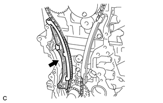
Remove the chain tensioner slipper.
-
-
REMOVE NO. 1 CHAIN VIBRATION DAMPER
-
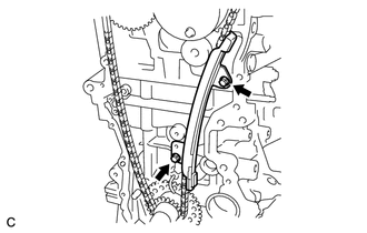
Remove the 2 bolts and No. 1 chain vibration damper.
-
-
REMOVE CHAIN SUB-ASSEMBLY
-
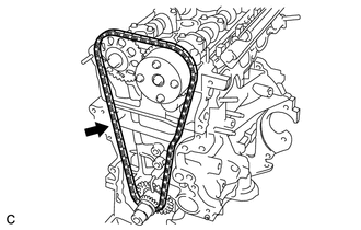
Remove the chain sub-assembly.
Note
When rotating the camshaft with the chain sub-assembly removed, rotate the crankshaft counterclockwise 40° from TDC and align the oil jet hole with the paint mark to prevent the pistons from coming into contact with the valves.
-
-
REMOVE CAMSHAFT
-
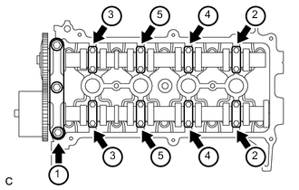
Using several steps, uniformly loosen and remove the 19 bolts in the sequence shown in the illustration, then remove the No. 1 camshaft bearing cap and 8 No. 2 camshaft bearing caps.
Note
Uniformly loosen the bolts while keeping the camshaft level.
-
Remove the camshaft and No. 2 camshaft.
-
-
REMOVE CYLINDER HEAD SUB-ASSEMBLY
-
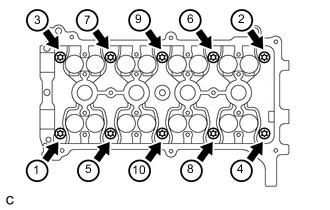
Using several steps, uniformly loosen and remove the 10 cylinder head bolts and 10 washers with an 8 mm bi-hexagon wrench in the sequence shown in the illustration.
Note
-
When removing the cylinder head bolt, do not drop the washer into the cylinder head sub-assembly.
-
Removing the bolts in the wrong order may cause damage to the cylinder head sub-assembly.
-
-
Remove the cylinder head sub-assembly.
-
-
REMOVE CYLINDER HEAD GASKET
-
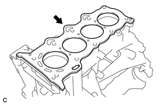
Remove the cylinder head gasket from the cylinder block.
-