CAMSHAFT REMOVAL
PROCEDURE
-
REMOVE EGR COOLER ASSEMBLY
-
SEPARATE BRAKE MASTER CYLINDER RESERVOIR ASSEMBLY (for RHD)
-
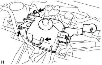
Disconnect the connector.
-
Remove the bolt and nut, and separate the brake master cylinder reservoir assembly.
-
-
REMOVE NO. 1 IGNITION COIL
-
SEPARATE ENGINE WIRE (for LHD)
-
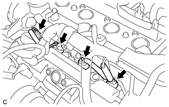
Disconnect the 4 injector connectors.
-
Disconnect the wire harness clamp.
-
Remove the 2 bolts, nut and separate the engine wire.
-
-
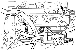
SEPARATE ENGINE WIRE (for RHD)
-
Disconnect the 4 injector connectors.
-
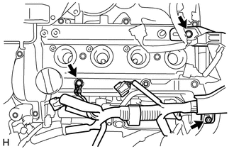
Remove the 2 bolts, nut and separate the engine wire.
-
-
REMOVE ENGINE COVER BRACKET
-
Remove the 2 bolts and engine cover bracket.
-
-
REMOVE CYLINDER HEAD COVER SUB-ASSEMBLY
-
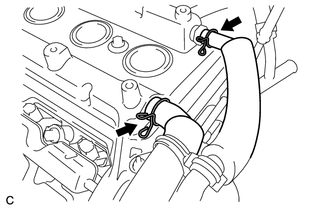
Disconnect the No. 1 ventilation hose and No. 2 ventilation hose.
-
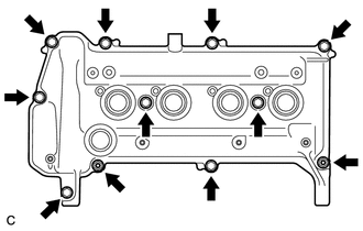
Remove the 9 bolts, 2 seal washers, 2 nuts and cylinder head cover sub-assembly.
-
Remove the gasket from the cylinder head cover sub-assembly.
-
-
SET NO. 1 CYLINDER TO TDC / COMPRESSION
-
REMOVE SCREW PLUG
-
REMOVE NO. 2 CAMSHAFT
-
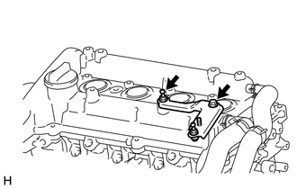
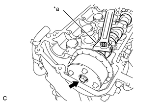
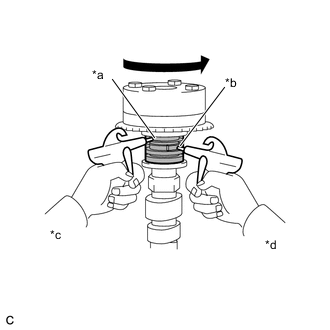
Text in Illustration *a Hold Loosen the bolts on the camshaft timing gear or sprocket while holding the hexagonal portion of the No. 2 camshaft.
-
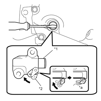
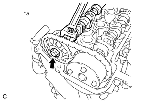
Text in Illustration *1 Plunger *2 Stopper Plate *a Unlock Insert a screwdriver from the plug hole and turn the stopper plate of the No. 1 chain tensioner assembly clockwise to release the lock, and keep it as it is.
Tech Tips
-
The plunger of the No. 1 chain tensioner assembly is locked.
-
If the stopper plate is locked firmly, slightly turn the hexagonal portion of the camshaft to the right and left.
-
-
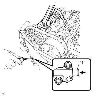
Text in Illustration *1 Plunger Slightly turn the hexagonal portion of the No. 2 camshaft clockwise so that the plunger of the No. 1 chain tensioner assembly is pushed by the chain sub-assembly.
-
Insert a screwdriver from the plug hole and turn the stopper plate of the No. 1 chain tensioner assembly counterclockwise to the lock, and keep it as it is. Insert the hexagon wrench into the stopper plate hole.
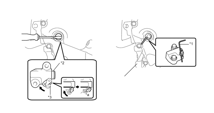
Text in Illustration *1 Hexagon Wrench *2 Plunger *3 Stopper Plate *a Lock Tech Tips
Hold the hexagon wrench with tape so that the hexagon wrench does not come off.
-
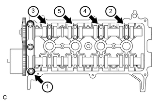
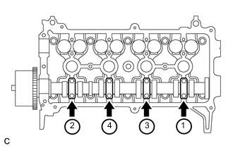
Using several steps, uniformly loosen and remove the 11 bolts in the sequence shown in the illustration. Then remove the No. 1 camshaft bearing cap and 4 No. 2 camshaft bearing caps.
Note
Uniformly loosen the bolts while keeping the No. 2 camshaft level.
-
Remove the bolt with the No. 2 camshaft lifted up.
-
Remove the No. 2 camshaft and camshaft timing gear or sprocket.
-
-
REMOVE CAMSHAFT
-
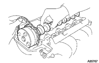
Text in Illustration *a Hold Loosen the bolts on the camshaft timing gear assembly while holding the hexagonal portion of the camshaft.
-
Using several steps, uniformly loosen and remove the 8 bolts in the sequence shown in the illustration. Then remove the 4 No. 2 camshaft bearing caps.
Note
Uniformly loosen the bolts while keeping the camshaft level.
-
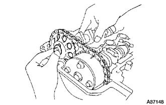
Hold the chain sub-assembly with one hand, and remove the camshaft.
-
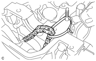
Tie the chain sub-assembly with a string or similar as shown in the illustration.
Note
Be careful not to drop anything inside the timing chain cover.
-
-
INSPECT CAMSHAFT TIMING GEAR ASSEMBLY
-
Check the camshaft timing gear assembly lock.
-
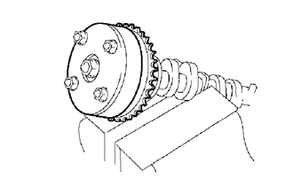
Clamp the camshaft in a vise, and make sure that the camshaft timing gear assembly does not rotate.
-
-
Release the lock pin.
-
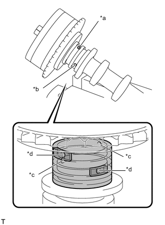
Text in Illustration *a Retard Side Path *b Advance Side Path *c Open *d Close 
Rubber Piece 
Vinyl Tape Cover the 4 oil paths of the cam journal with vinyl tape as shown in the illustration.
Tech Tips
4 oil paths are provided in the groove. Plug 2 paths with rubber pieces.
-
Prick a hole in the tape placed on the advance side path. Prick a hole in the tape placed on the retard side path, on the opposite side to that of the advance side path, as shown in the illustration.
-
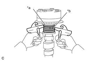
Text in Illustration *a Advance Side Path *b Retard Side Path Apply approximately 150 kPa (1.5 kgf/cm2, 22 psi) of air pressure to the 2 paths (the advance side path and the retard side path).
Tech Tips
Cover the paths with a piece of cloth when applying pressure to keep oil from splashing.
-
Text in Illustration *a Advance Side Path *b Retard Side Path *c Decompress *d Hold Pressure Make sure that the camshaft timing sprocket turns in the retard direction when reducing the air pressure applied to the advance side path.
Tech Tips
The lock pin is released and the camshaft timing sprocket turns in the retard direction.
-
When the camshaft timing sprocket moves to the most retarded position, release the air pressure from the advance side path, and then release the air pressure from the retard side path.
Note
Be sure to release the air pressure from the advance side path first. If the air pressure of the retard side path is released first, the camshaft timing sprocket may abruptly shift in the advance direction and break the lock pin or other parts.
-
-
-
REMOVE CAMSHAFT TIMING GEAR ASSEMBLY
-
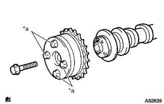
Text in Illustration *a Do Not Remove Remove the bolt and camshaft timing gear assembly.
Note
-
Be sure not to remove the other 4 bolts.
-
When reusing the camshaft timing gear assembly, release the lock pin first, then install the camshaft timing gear assembly.
-
-