CAMSHAFT INSTALLATION
CAUTION / NOTICE / HINT
Tech Tips
Perform "Inspection After Repairs" after replacing the camshaft timing gear assembly, camshaft or No. 2 camshaft Click here.
PROCEDURE
-
INSTALL CAMSHAFT TIMING GEAR ASSEMBLY
Tech Tips
Perform "Inspection After Repairs" after replacing the camshaft timing gear assembly Click here.
-
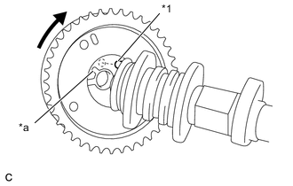
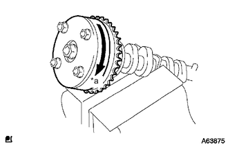
Text in Illustration *1 Straight Pin *a Key Groove Put the camshaft timing gear assembly and camshaft together with the straight pin and key groove misaligned as shown in the illustration.
-
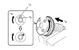
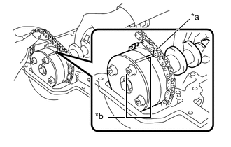
Text in Illustration *a View A *b Straight Pin *c Key Groove Turn the camshaft timing gear assembly as shown in the illustration while pushing it gently against the camshaft. Push further at the position where the pin fits into the groove.
Note
Be sure not to turn the camshaft timing gear assembly to the retard direction (clockwise).
-
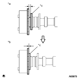
Text in Illustration *a INCORRECT *b CORRECT *c Flange Check that there is no clearance between the camshaft timing gear assembly and camshaft flange.
-
Tighten the bolt with the camshaft timing gear assembly secured in place.
- Torque:
- 64 N*m { 652 kgf*cm, 47 ft.*lbf }
Note
-
Do not lock the camshaft timing gear assembly when tightening the bolt.
-
Release the lock pin of the camshaft timing gear assembly first, and tighten the bolt when the lock pin is locked in the most retarded position.
-
Tightening the bolts with the lock pin locked could cause breakage of the lock pin.
-
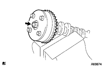
Text in Illustration *a Lock Check that the camshaft timing gear assembly can move to the retard direction (clockwise) and is locked in the most retarded position.
-
-
INSTALL CAMSHAFT
Tech Tips
Perform "Inspection After Repairs" after replacing the camshaft Click here.
-
Apply a light coat of engine oil to the camshaft journals and cylinder head sub-assembly journals.
-
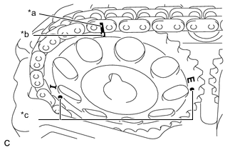
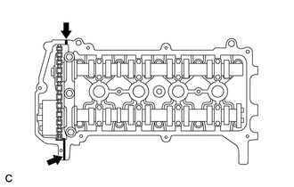
Text in Illustration *a Paint Mark *b Timing Mark Install the chain sub-assembly onto the camshaft timing gear assembly with the paint mark on the chain sub-assembly aligned with the timing mark on the camshaft timing gear assembly as shown in the illustration.
-
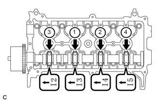
Examine the front marks and numbers, and tighten the 4 No. 2 camshaft bearing caps with the 8 bolts in the sequence shown in the illustration.
- Torque:
- 13 N*m { 129 kgf*cm, 9 ft.*lbf }
Note
Tighten each bolt uniformly, keeping the camshaft level.
-
-
INSTALL NO. 2 CAMSHAFT
Tech Tips
Perform "Inspection After Repairs" after replacing the No. 2 camshaft Click here.
-
Apply a light coat of engine oil to the No. 2 camshaft journals and cylinder head sub-assembly journals.
-
Text in Illustration *a Paint Mark *b Timing Mark (Rectangle) *c Mark (Circle) Put the camshaft timing gear or sprocket on the cylinder head sub-assembly with the paint mark on the chain sub-assembly aligned with the timing mark on the camshaft timing gear or sprocket.
Tech Tips
There are 3 marks on the camshaft timing gear or sprocket. Make sure to align the mark plate with the timing mark (rectangle).
-
While holding the No. 2 camshaft by hand, temporarily install the No. 2 camshaft to the camshaft timing gear or sprocket using the bolt.
-
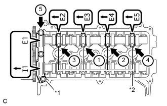
Text in Illustration *1 No. 1 Camshaft Bearing Cap *2 No. 2 Camshaft Bearing Cap Examine the front marks and numbers, and tighten the No. 1 camshaft bearing cap and No. 2 camshaft bearing caps with the 11 bolts in the sequence shown in the illustration.
- Torque:
- No. 2 camshaft bearing cap
- 13 N*m { 129 kgf*cm, 9 ft.*lbf }
- No. 1 camshaft bearing cap
- 23 N*m { 234 kgf*cm, 17 ft.*lbf }
Note
Tighten each bolt uniformly, keeping the No. 2 camshaft level.
-
Using a 14 mm union nut wrench, tighten the bolts onto the camshaft timing gear or sprocket while holding the hexagonal portion of the No. 2 camshaft.
- Torque:
- 64 N*m { 652 kgf*cm, 47 ft.*lbf }
Note
Use the torque value compensation formula to calculate the torque value for use when a torque wrench is combined with a tool such as a union nut wrench Click here.
-
Remove the hexagon wrench from the No. 1 chain tensioner assembly.
-
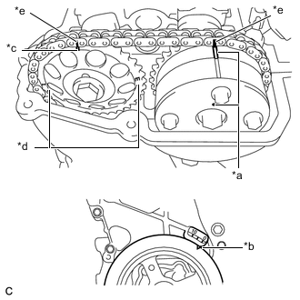
Text in Illustration *a Timing Mark *b Timing Notch *c Timing Mark (Rectangle) *d Mark (Circle) *e Paint Mark Turn the crankshaft damper until its notch and timing mark "0" of the timing chain cover are aligned.
Tech Tips
There are 3 marks on the camshaft timing gear or sprocket. Make sure that the timing mark (rectangle) is at the top.
-
Check that all the pairs of timing marks are aligned.
-
-
INSTALL SCREW PLUG
-
INSTALL CYLINDER HEAD COVER SUB-ASSEMBLY
-
Install a new gasket to the cylinder head cover sub-assembly.
-
Apply seal packing to the 2 locations shown in the illustration.
Text in Illustration 
Apply Seal Packing Seal packing Toyota Genuine Seal Packing Black, Three Bond 1207B or equivalent Note
-
Remove any oil from the contact surface.
-
Install the cylinder head cover within 3 minutes of applying seal packing.
-
Do not start the engine for at least 2 hours after installation.
-
-
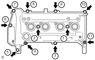
Text in Illustration *1 Seal Washer Temporarily install the cylinder head cover sub-assembly with the 9 bolts, 2 nuts and 2 new seal washers.
-
Using several steps, uniformly tighten the bolts and nuts in the sequence shown in the illustration.
- Torque:
- 13 N*m { 132 kgf*cm, 10 ft.*lbf }
-
Connect the No. 1 ventilation hose and No. 2 ventilation hose.
-
-
INSTALL ENGINE COVER BRACKET
-
Install the engine cover bracket with the 2 bolts.
- Torque:
- 10 N*m { 102 kgf*cm, 7 ft.*lbf }
-
-
CONNECT ENGINE WIRE (for LHD)
-
Install the engine wire with the 2 bolts and nut.
- Torque:
- 8.4 N*m { 85 kgf*cm, 74 in.*lbf }
-
Connect the wire harness clamp.
-
Connect the 4 injector connectors.
-
-
CONNECT ENGINE WIRE (for RHD)
-
Install the engine wire with the 2 bolts and nut.
- Torque:
- 8.4 N*m { 85 kgf*cm, 74 in.*lbf }
-
Connect the 4 injector connectors.
-
-
INSTALL NO. 1 IGNITION COIL
-
INSTALL BRAKE MASTER CYLINDER RESERVOIR ASSEMBLY (for RHD)
-
Install the brake master cylinder reservoir assembly with the bolt and nut.
- Torque:
- 8.0 N*m { 82 kgf*cm, 71 in.*lbf }
-
Connect the connector.
-
-
INSTALL EGR COOLER ASSEMBLY