VALVE CLEARANCE ADJUSTMENT
PROCEDURE
-
REMOVE CYLINDER HEAD COVER SUB-ASSEMBLY
-
SET NO. 1 CYLINDER TO TDC / COMPRESSION
-
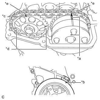
Text in Illustration *a Timing Mark *b Timing Notch *c Timing Mark (Rectangle) *d Mark (Circle) *e Paint Mark Turn the crankshaft damper until its notch and timing mark "0" of the timing chain cover are aligned.
-
Check that the timing marks on both the camshaft timing gear or sprocket and the camshaft timing gear assembly are facing upward as shown in the illustration.
Tech Tips
-
If not, turn the crankshaft 1 complete revolution (360°) and align the marks as above.
-
There are 3 marks on the camshaft timing gear or sprocket. Make sure that the timing mark (rectangle) is at the top.
-
-
Place paint marks on the chain sub-assembly in alignment with the timing marks on the camshaft timing gear assembly and camshaft timing gear or sprocket.
-
-
INSPECT VALVE CLEARANCE
-
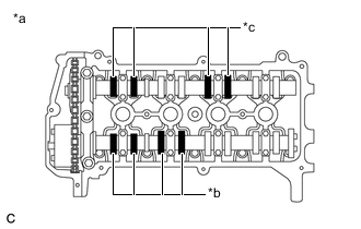
Text in Illustration *a No. 1 Cylinder TDC/Compression *b Intake Side *c Exhaust Side Check only the valves indicated.
-
Using a feeler gauge, measure the clearance between the valve lifter and camshaft.
Standard Valve Clearance (Cold) Item Specified Condition Intake 0.15 to 0.25 mm (0.00591 to 0.00984 in.) Exhaust 0.25 to 0.35 mm (0.00984 to 0.0138 in.) Tech Tips
Record any out-of-specification valve clearance measurements. They will be used later to determine the required replacement valve lifters.
-
-
Turn the crankshaft 1 revolution (360°) and set the No. 4 cylinder to TDC/compression.
-
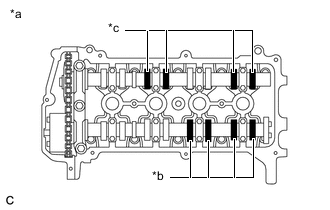
Text in Illustration *a No. 4 Cylinder TDC/Compression *b Intake Side *c Exhaust Side Check only the valves indicated.
-
Using a feeler gauge, measure the clearance between the valve lifter and camshaft.
Standard Valve Clearance (Cold) Item Specified Condition Intake 0.15 to 0.25 mm (0.00591 to 0.00984 in.) Exhaust 0.25 to 0.35 mm (0.00984 to 0.0138 in.) Tech Tips
Record any out-of-specification valve clearance measurements. They will be used later to determine the required replacement valve lifters.
-
-
-
ADJUST VALVE CLEARANCE
-
Remove the camshaft Click here.
-
Remove the valve lifters.
Tech Tips
Arrange the valve lifters in the same order as removed.
-
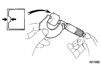
Using a micrometer, measure the thickness of the removed valve lifters.
-
Calculate the thickness of a new valve lifter so that the valve clearance comes within the specified range.
New Valve Lifter Thickness Item Specification Intake A = B + (C - 0.20 mm (0.00787 in.)) Exhaust A = B + (C - 0.30 mm (0.0118 in.)) A New valve lifter thickness B Used valve lifter thickness C Measured valve clearance CALCULATION EXAMPLE (Intake):
-
Measured intake valve clearance = 0.40 mm (0.0157 in.)
(Measured - Specification = Excess clearance)
-
0.40 mm (0.0157 in.) - 0.20 mm (0.00787 in.) = 0.20 mm (0.00787 in.)
-
Measured used valve lifter thickness = 5.250 mm (0.207 in.)
-
New valve lifter thickness = 5.450 mm (0.21457 in.)
(Excess clearance + Used valve lifter thickness = Ideal new valve lifter)
-
0.20 mm (0.00787 in.) + 5.250 mm (0.207 in.) = 5.450 mm (0.21457 in.)
-
Closest new valve lifter = 5.460 mm (0.21496 in.)
-
Select No. 42 valve lifter
-
-
Select a new lifter with a thickness as close as possible to the calculated values.
Tech Tips
-
Lifters are available in 35 sizes in increments of 0.020 mm (0.000787 in.), from 5.060 to 5.740 mm (0.1992 to 0.2260 in.).
-
Refer to the new valve lifter thickness table below.
-
Valve lifter selection chart (intake).
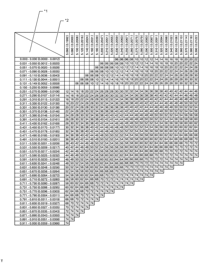
*1 Measured Valve Clearance mm (in.) *2 Installed Valve Lifter Thickness mm (in.) -
Valve lifter selection chart (intake) (continued).
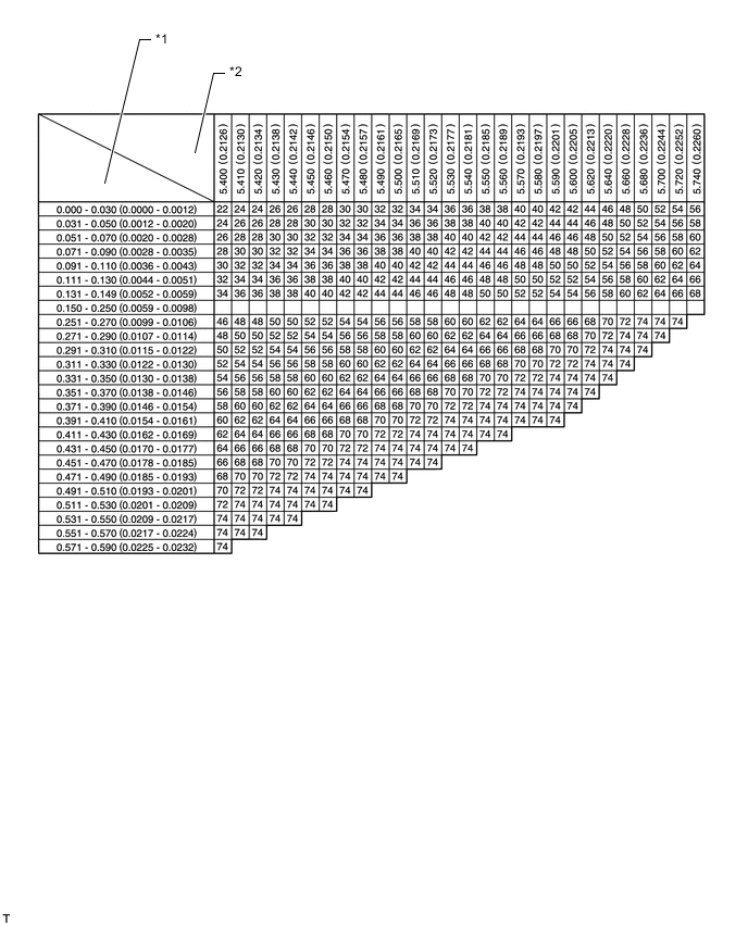
*1 Measured Valve Clearance mm (in.) *2 Installed Valve Lifter Clearance mm (in.) New lifter thickness Lifter No. Thickness Lifter No. Thickness Lifter No. Thickness 06 5.060 mm (0.1992 in.) 30 5.300 mm (0.2087 in.) 54 5.540 mm (0.2181 in.) 08 5.080 mm (0.2000 in.) 32 5.320 mm (0.2094 in.) 56 5.560 mm (0.2189 in.) 10 5.100 mm (0.2008 in.) 34 5.340 mm (0.2102 in.) 58 5.580 mm (0.2197 in.) 12 5.120 mm (0.2016 in.) 36 5.360 mm (0.2110 in.) 60 5.600 mm (0.2205 in.) 14 5.140 mm (0.2024 in.) 38 5.380 mm (0.2118 in.) 62 5.620 mm (0.2213 in.) 16 5.160 mm (0.2031 in.) 40 5.400 mm (0.2126 in.) 64 5.640 mm (0.2220 in.) 18 5.180 mm (0.2039 in.) 42 5.420 mm (0.2134 in.) 66 5.660 mm (0.2228 in.) 20 5.200 mm (0.2047 in.) 44 5.440 mm (0.2142 in.) 68 5.680 mm (0.2236 in.) 22 5.220 mm (0.2055 in.) 46 5.460 mm (0.2150 in.) 70 5.700 mm (0.2244 in.) 24 5.240 mm (0.2063 in.) 48 5.480 mm (0.2157 in.) 72 5.720 mm (0.2252 in.) 26 5.260 mm (0.2071 in.) 50 5.500 mm (0.2165 in.) 74 5.740 mm (0.2260 in.) 28 5.280 mm (0.2079 in.) 52 5.520 mm (0.2173 in.) - - Standard intake valve clearance (Cold) 0.15 to 0.25 mm (0.00591 to 0.00984 in.) EXAMPLE:
A 5.250 mm (0.207 in.) valve lifter is installed, and the measured clearance is 0.400 mm (0.0157 in.).
Replace the 5.250 mm (0.207 in.) valve lifter with a new No. 46 valve lifter.
-
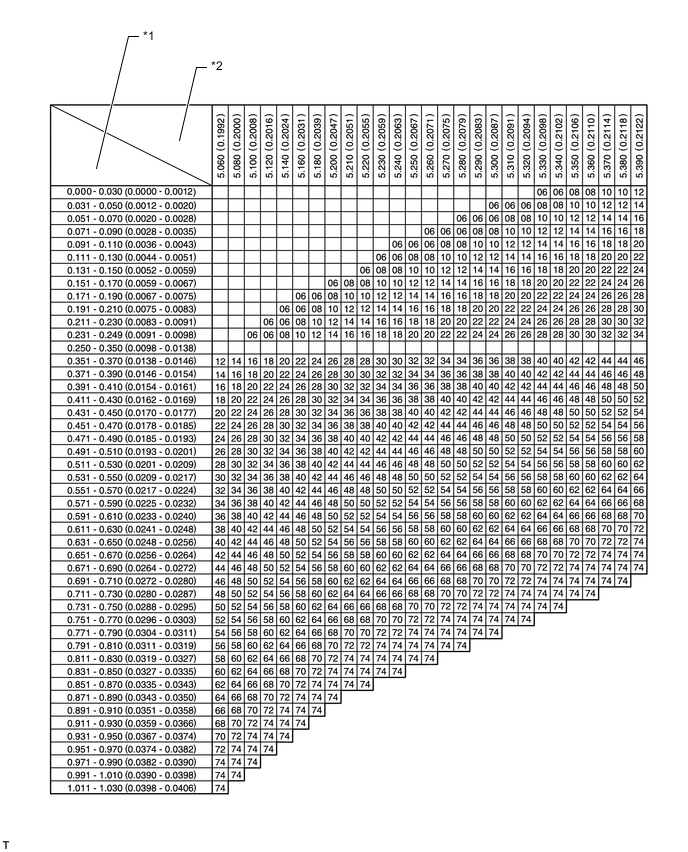
Valve lifter selection chart (exhaust).
*1 Measured Valve Clearance mm (in.) *2 Installed Valve Lifter Thickness mm (in.) -
Valve selection chart (exhaust) (continued).
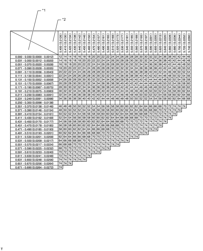
*1 Measured Valve Clearance mm (in.) *2 Installed Valve Lifter Clearance mm (in.) New lifter thickness Lifter No. Thickness Lifter No. Thickness Lifter No. Thickness 06 5.060 mm (0.1992 in.) 30 5.300 mm (0.2087 in.) 54 5.540 mm (0.2181 in.) 08 5.080 mm (0.2000 in.) 32 5.320 mm (0.2094 in.) 56 5.560 mm (0.2189 in.) 10 5.100 mm (0.2008 in.) 34 5.340 mm (0.2102 in.) 58 5.580 mm (0.2197 in.) 12 5.120 mm (0.2016 in.) 36 5.360 mm (0.2110 in.) 60 5.600 mm (0.2205 in.) 14 5.140 mm (0.2024 in.) 38 5.380 mm (0.2118 in.) 62 5.620 mm (0.2213 in.) 16 5.160 mm (0.2031 in.) 40 5.400 mm (0.2126 in.) 64 5.640 mm (0.2220 in.) 18 5.180 mm (0.2039 in.) 42 5.420 mm (0.2134 in.) 66 5.660 mm (0.2228 in.) 20 5.200 mm (0.2047 in.) 44 5.440 mm (0.2142 in.) 68 5.680 mm (0.2236 in.) 22 5.220 mm (0.2055 in.) 46 5.460 mm (0.2150 in.) 70 5.700 mm (0.2244 in.) 24 5.240 mm (0.2063 in.) 48 5.480 mm (0.2157 in.) 72 5.720 mm (0.2252 in.) 26 5.260 mm (0.2071 in.) 50 5.500 mm (0.2165 in.) 74 5.740 mm (0.2260 in.) 28 5.280 mm (0.2079 in.) 52 5.520 mm (0.2173 in.) - - Standard exhaust valve clearance (Cold) 0.25 to 0.35 mm (0.00984 to 0.01378 in.) EXAMPLE:
A 5.340 mm (0.210 in.) valve lifter is installed, and the measured clearance is 0.440 mm (0.0173 in.).
Replace the 5.340 mm (0.210 in.) valve lifter with a new No. 48 valve lifter.
-
-
Install the selected valve lifter.
-
Install the camshaft Click here.
-
-
INSTALL CYLINDER HEAD COVER SUB-ASSEMBLY