HV RELAY ASSEMBLY INSTALLATION
PROCEDURE
-
INSTALL HYBRID BATTERY JUNCTION BLOCK ASSEMBLY
CAUTION:
Wear insulated gloves.
-
Install the hybrid battery junction block assembly with the 3 bolts.
- Torque:
- 7.5 N*m { 76 kgf*cm, 66 in.*lbf }
-
Connect the connector to the hybrid battery junction block assembly.
Note
The connector should be connected securely.
-
Using an insulated tool, install the 2 bolts.
- Torque:
- 5.4 N*m { 55 kgf*cm, 48 in.*lbf }
Note
Be sure to use a torque wrench to tighten the bolts.
-
Connect the terminal cover.
Note
The terminal cover should be connected securely.
-
-
INSTALL NO. 2 HYBRID BATTERY SHIELD SUB-ASSEMBLY
CAUTION:
Wear insulated gloves.
-
Install the No. 2 hybrid battery shield sub-assembly with the 2 bolts and nut.
- Torque:
- 7.5 N*m { 76 kgf*cm, 66 in.*lbf }
-
Move the HV battery to the installation position.
-
Install the HV battery with the 2 bolts and 2 nuts.
- Torque:
- 19 N*m { 194 kgf*cm, 14 ft.*lbf }
-
-
CONNECT FRAME WIRE
CAUTION:
Wear insulated gloves.
-
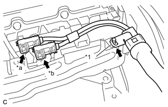
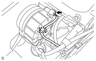
Text in Illustration *1 Shielded Wire Ground *a White Connector *b Orange Connector Connect the 2 connectors.
Note
-
Make sure that the ends of the frame wire do not cross over each other.
-
The connector should be connected securely.
-
-
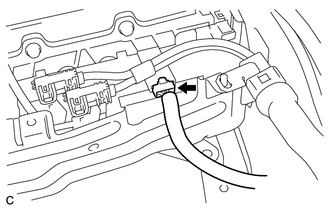
Connect the shielded wire ground.
-
-
CONNECT WIRE HARNESS
-
Disconnect the connector as shown in the illustration.
-
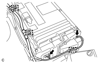
Disconnect the 2 connectors and 3 clamps as shown in the illustration.
-
Disconnect the connector and wire harness clamp as shown in the illustration.
-
-
INSTALL NO. 1 HYBRID VEHICLE BATTERY COVER PANEL LH
CAUTION:
Wear insulated gloves.
-
Install the No. 1 hybrid vehicle battery cover panel LH with the 4 nuts.
- Torque:
- 7.5 N*m { 76 kgf*cm, 66 in.*lbf }
-
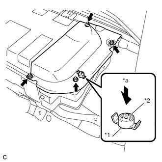
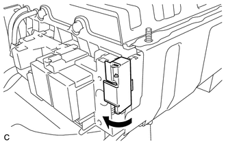
Text in Illustration *1 Battery Cover Lock Striker *2 Button *a Push Install the battery cover lock striker, then push the button to lock it.
-
-
INSTALL NO. 1 HYBRID BATTERY EXHAUST DUCT
-
INSTALL NO. 2 INDOOR ELECTRICAL KEY ANTENNA ASSEMBLY (w/ Smart Entry)
-
INSTALL REAR SEAT CUSHION LEG SUB-ASSEMBLY
-
INSTALL BENCH TYPE REAR SEAT CUSHION ASSEMBLY
-
INSTALL SERVICE PLUG GRIP
-
CONNECT CABLE TO NEGATIVE AUXILIARY BATTERY TERMINAL
-
INSTALL CENTER FRONT FLOOR COVER (for Front Floor Cover Type A)
-
INSTALL FRONT FLOOR COVER LH (for Front Floor Cover Type A)
-
INSTALL FRONT FLOOR COVER RH (for Front Floor Cover Type A)
-
INSTALL FRONT FLOOR COVER LH (for Front Floor Cover Type B)
-
INSTALL FRONT FLOOR COVER RH (for Front Floor Cover Type B)
-
INSTALL CENTER FRONT FLOOR COVER (for Front Floor Cover Type B)