HV RELAY ASSEMBLY REMOVAL
PROCEDURE
-
PRECAUTION
-
REMOVE FRONT FLOOR COVER RH (for Front Floor Cover Type A)
-
REMOVE FRONT FLOOR COVER LH (for Front Floor Cover Type A)
-
REMOVE CENTER FRONT FLOOR COVER (for Front Floor Cover Type A)
-
REMOVE CENTER FRONT FLOOR COVER (for Front Floor Cover Type B)
-
REMOVE FRONT FLOOR COVER RH (for Front Floor Cover Type B)
-
REMOVE FRONT FLOOR COVER LH (for Front Floor Cover Type B)
-
DISCONNECT CABLE FROM NEGATIVE AUXILIARY BATTERY TERMINAL
-
REMOVE SERVICE PLUG GRIP
-
REMOVE BENCH TYPE REAR SEAT CUSHION ASSEMBLY
-
REMOVE REAR SEAT CUSHION LEG SUB-ASSEMBLY
-
REMOVE HOOD STAY HOLDER
-
REMOVE INVERTER TERMINAL COVER
-
REMOVE INVERTER COVER
-
CHECK TERMINAL VOLTAGE
-
INSTALL INVERTER COVER
-
INSTALL INVERTER TERMINAL COVER
-
INSTALL HOOD STAY HOLDER
-
REMOVE NO. 2 INDOOR ELECTRICAL KEY ANTENNA ASSEMBLY (w/ Smart Entry)
-
REMOVE NO. 1 HYBRID BATTERY EXHAUST DUCT
-
REMOVE NO. 1 HYBRID VEHICLE BATTERY COVER PANEL LH
CAUTION:
Wear insulated gloves.
-
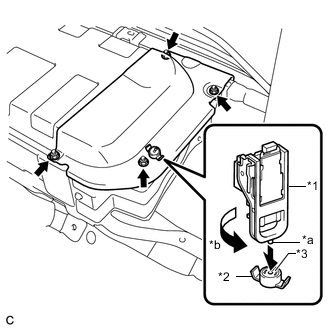
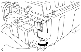
Text in Illustration *1 Service Plug Grip *2 Battery Cover Lock Striker *3 Button *a Projection *b Turn Using the service plug grip, remove the battery cover lock striker.
Tech Tips
Insert the projection part of the service plug grip, and turn the button of the battery cover lock striker counterclockwise, and release the lock.
-
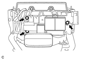
Remove the 4 nuts and No. 1 hybrid vehicle battery cover panel LH.
-
-
DISCONNECT WIRE HARNESS
-
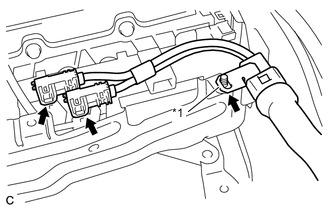
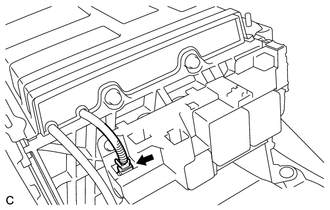
Disconnect the connector and wire harness clamp.
-
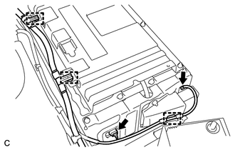
Disconnect the 2 connectors and 3 clamps.
-
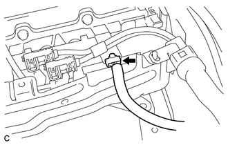
Disconnect the connector.
-
-
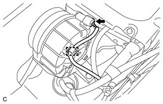
DISCONNECT FRAME WIRE
CAUTION:
Wear insulated gloves.
Note
Insulate the disconnected connectors with insulating tape.
-
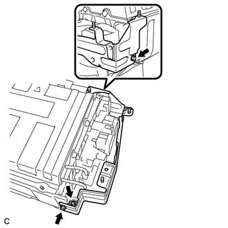
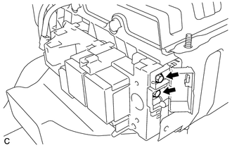
Text in Illustration *1 Shielded Wire Ground Disconnect the 2 connectors shown in the illustration.
-
Disconnect the shielded wire ground and frame wire.
-
-
REMOVE NO. 2 HYBRID BATTERY SHIELD SUB-ASSEMBLY
CAUTION:
Wear insulated gloves.
-
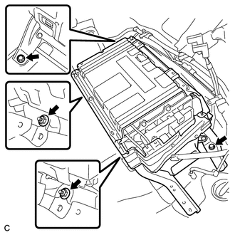
Remove the 2 bolts and 2 nuts.
-
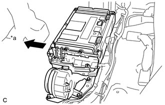
Text in Illustration *a Front of Vehicle Move the HV battery toward the front of the vehicle.
Tech Tips
Move the HV battery to a position where both the No. 2 hybrid battery shield sub-assembly and the hybrid battery junction block assembly can be removed.
-
Remove the 2 bolts, nut and No. 2 hybrid battery shield sub-assembly.
-
-
REMOVE HYBRID BATTERY JUNCTION BLOCK ASSEMBLY
CAUTION:
Wear insulated gloves.
Note
Insulate the disconnected terminals with insulating tape.
-
Open the terminal cover.
-
Using an insulated tool, remove the 2 bolts.
-
Disconnect the connector.
-
Remove the 3 bolts and hybrid battery junction block assembly.
-