FRAME WIRE INSTALLATION
PROCEDURE
-
INSTALL FRAME WIRE
CAUTION:
Wear insulated gloves.
Note
Insulate the removed terminals with insulating tape.
-
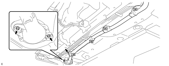
Install a frame wire with the 4 new clamps as shown in the illustration.
-
Insert the frame wire into the floor panel hole.
-
Install the 3 nuts as shown in the illustration.
- Torque:
- 8.4 N*m { 86 kgf*cm, 74 in.*lbf }
-
Connect the clamp as shown in the illustration.
-
Connect the clamp as shown in the illustration.
-
Connect the clamp as shown in the illustration.
-
Connect the clamp as shown in the illustration.
-
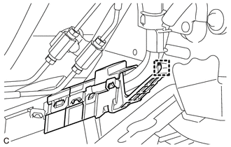
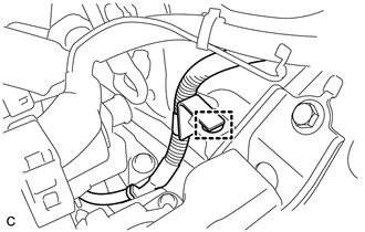
Connect the frame wire with the claw as shown in the illustration.
-
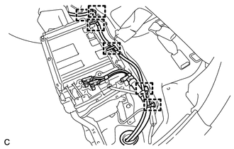
Connect the 6 clamps as shown in the illustration.
-
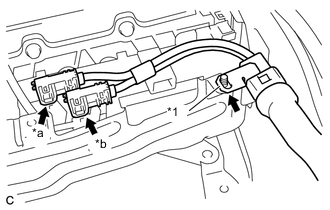
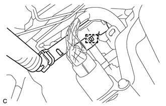
Text in Illustration *1 Shielded Wire Ground *a White Connector *b Orange Connector Connect the 2 connectors as shown in the illustration.
Note
-
Make sure that the ends of the frame wire are not crossed over each other.
-
Be sure to connect the ends of the frame wire to the correct terminals.
-
-
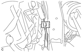
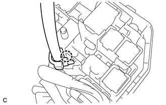
Connect the shielded wire ground as shown in the illustration.
-
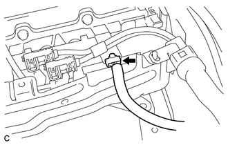
Connect the connector as shown in the illustration.
-
-
CONNECT CABLE TO POSITIVE AUXILIARY BATTERY TERMINAL
-
Connect the positive auxiliary battery terminal with the nut.
- Torque:
- 7.6 N*m { 77 kgf*cm, 67 in.*lbf }
-
Install the terminal cover.
-
-
INSTALL NO. 1 HYBRID BATTERY EXHAUST DUCT
-
INSTALL NO. 1 HYBRID VEHICLE BATTERY COVER PANEL LH
-
INSTALL BATTERY COOLING BLOWER ASSEMBLY
-
INSTALL REAR SEAT CUSHION LEG SUB-ASSEMBLY
-
INSTALL BENCH TYPE REAR SEAT CUSHION ASSEMBLY
-
INSTALL FRONT SUSPENSION CROSSMEMBER SUB-ASSEMBLY
-
INSTALL INVERTER BRACKET ASSEMBLY
-
INSTALL INVERTER WITH CONVERTER ASSEMBLY