ENGINE UNIT REASSEMBLY

PROCEDURE
-
INSTALL OIL PAN SUB-ASSEMBLY
Tech Tips
If a stud bolt is deformed or the threads are damaged, replace it.
-
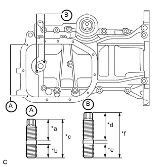
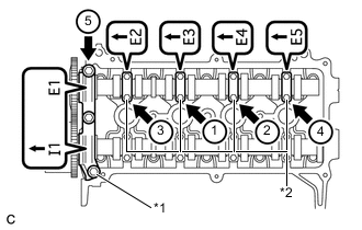
Text in Illustration *a 13 mm (0.512 in.) *b 8 mm (0.315 in.) *c 22.5 mm (0.886 in.) *d 16.5 mm (0.650 in.) *e 9 mm (0.354 in.) *f 27.5 mm (1.08 in.) Using an E5 "TORX" socket wrench, install the 4 stud bolts.
- Torque:
- 5.0 N*m { 51 kgf*cm, 44 in.*lbf }
-
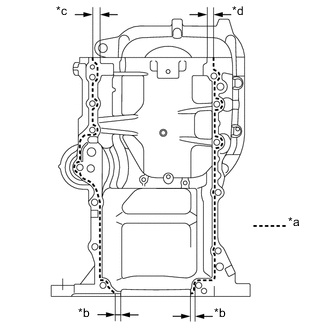
Text in Illustration *a Apply Seal Packing *b 4 mm (0.157 in.) *c 11 mm (0.433 in.) *d 9 mm (0.354 in.) Apply seal packing to the oil pan sub-assembly as shown in the illustration.
Seal packing Toyota Genuine Seal Packing Black, Three Bond 1207B or equivalent Standard seal diameter 2.0 to 3.0 mm (0.0787 to 0.118 in.) Note
-
Clean the surfaces with non-residue solvent before applying seal packing.
-
Install the oil pan sub-assembly within 3 minutes and tighten the bolts within 15 minutes of applying seal packing.
-
Do not apply engine oil for at least 2 hours after installation.
-
-
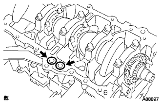
Install 2 new O-rings to the cylinder block and temporarily install the oil pan sub-assembly with the 13 bolts.
Note
-
Clean the surfaces with non-residue solvent before applying seal packing.
-
Be careful that the O-ring is not cracked or moved out of place when installing the oil pan sub-assembly.
-
-
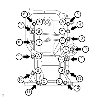
Using several steps, uniformly tighten the 13 bolts in the sequence shown in the illustration.
- Torque:
- 24 N*m { 245 kgf*cm, 18 ft.*lbf }
Item Length Of The Bolt From The Seat To The End. Bolt A 49 mm (1.93 in.) Bolt B 88 mm (3.46 in.) Bolt C 143.7 mm (5.66 in.)
-
-
INSTALL REAR ENGINE OIL SEAL
-
INSTALL OIL STRAINER SUB-ASSEMBLY
-
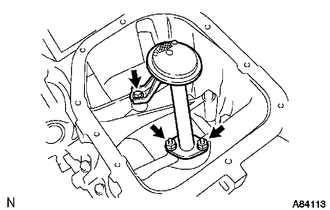
Install a new gasket and the oil strainer sub-assembly with the 2 nuts and bolt.
- Torque:
- 13 N*m { 132 kgf*cm, 10 ft.*lbf }
-
-
INSTALL NO. 2 OIL PAN SUB-ASSEMBLY
-
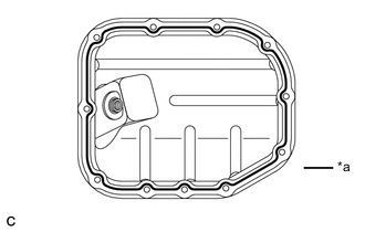
Text in Illustration *a Apply Seal Packing Apply seal packing to the No. 2 oil pan sub-assembly as shown in the illustration below.
Seal packing Toyota Genuine Seal Packing Black, Three Bond 1207B or equivalent Standard seal diameter 2.5 to 3.5 mm (0.0984 to 0.138 in.) Note
-
Clean the surfaces with non-residue solvent before applying seal packing.
-
Install the No. 2 oil pan sub-assembly within 3 minutes and tighten the bolts within 10 minutes of applying seal packing.
-
Do not apply engine oil for at least 2 hours after installation.
-
-
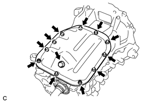
Install the No. 2 oil pan sub-assembly with the 9 bolts and 2 nuts.
- Torque:
- 9.0 N*m { 92 kgf*cm, 80 in.*lbf }
-
Install the oil pan drain plug with a new gasket.
- Torque:
- 38 N*m { 382 kgf*cm, 28 ft.*lbf }
-
-
INSTALL OIL FILTER UNION
-
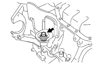
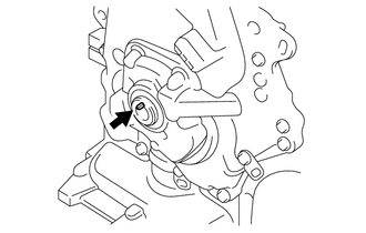
Using a 12 mm hexagon socket wrench, install the oil filter union.
- Torque:
- 30 N*m { 306 kgf*cm, 22 ft.*lbf }
-
-
INSTALL OIL FILTER SUB-ASSEMBLY
-
INSTALL CYLINDER HEAD GASKET
-
INSTALL CYLINDER HEAD SUB-ASSEMBLY
-
INSTALL CAMSHAFT TIMING GEAR ASSEMBLY
-
INSTALL CAMSHAFT
Tech Tips
Perform "Inspection After Repairs" after replacing the camshaft Click here.
-
Apply a light coat of engine oil to the camshaft and cylinder head sub-assembly journals.
-
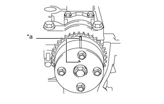
Text in Illustration *a Timing Mark Place the camshaft on the cylinder head sub-assembly with the timing mark on the camshaft timing gear assembly facing upward.
-
Examine the front marks and numbers, and tighten the 4 No. 2 camshaft bearing caps with the 8 bolts in the sequence shown in the illustration.
- Torque:
- 13 N*m { 129 kgf*cm, 9 ft.*lbf }
Note
Tighten each bolt uniformly, keeping the camshaft level.
-
-
INSTALL CAMSHAFT TIMING GEAR OR SPROCKET
-
Clamp the No. 2 camshaft in a vise.
Note
Be careful not to damage the No. 2 camshaft.
-
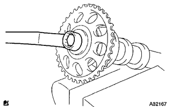
Align the knock pin hole of the camshaft timing gear or sprocket with the knock pin of the No. 2 camshaft, and tighten the camshaft timing gear or sprocket with the bolt.
- Torque:
- 64 N*m { 652 kgf*cm, 47 ft.*lbf }
-
-
INSTALL NO. 2 CAMSHAFT
Tech Tips
Perform "Inspection After Repairs" after replacing the No. 2 camshaft Click here.
-
Apply a light coat of engine oil to the No. 2 camshaft and cylinder head sub-assembly journals.
-
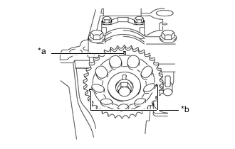
Text in Illustration *a Timing Mark (Rectangle) *b Mark (Circle) Place the No. 2 camshaft on the cylinder head with the timing mark on the camshaft timing gear or sprocket facing upward.
Tech Tips
There are 3 marks on the camshaft timing gear or sprocket. Make sure that the timing mark (rectangle) is at the top.
-
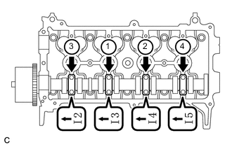
Text in Illustration *1 No. 1 Camshaft Bearing Cap *2 No. 2 Camshaft Bearing Cap Examine the front marks and numbers, and tighten the No. 1 camshaft bearing cap and No. 2 camshaft bearing caps with the 11 bolts in the sequence shown in the illustration.
- Torque:
- No. 2 camshaft bearing cap
- 13 N*m { 129 kgf*cm, 9 ft.*lbf }
- No. 1 camshaft bearing cap
- 23 N*m { 234 kgf*cm, 17 ft.*lbf }
Note
Tighten each bolt uniformly, keeping the No. 2 camshaft level.
-
-
INSTALL CHAIN SUB-ASSEMBLY
-
INSTALL OIL PUMP SEAL
-
INSTALL SCREW PLUG
-
INSTALL TIMING CHAIN COVER
-
INSTALL CRANKSHAFT DAMPER SUB-ASSEMBLY
-
Install the straight pin to the crankshaft.
-
Align the hole of the crankshaft damper sub-assembly with the straight pin, then install the crankshaft damper sub-assembly.
-
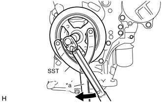
Text in Illustration *a Hold 
Turn Using SST, hold the crankshaft damper sub-assembly in place and tighten the bolt.
- SST
- 09960-10010 ( 09962-01000, 09963-01000 )
- Torque:
- 128 N*m { 1305 kgf*cm, 94 ft.*lbf }
Note
When installing SST, be careful that the bolt which holds SST does not interfere with the timing chain cover.
-
-
INSTALL ENGINE MOUNTING BRACKET RH
-
INSTALL WATER INLET HOUSING
-
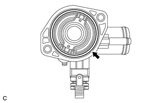
Install a new gasket to the water inlet housing.
-
Temporarily install the water inlet housing with the bolt and 2 nuts.
-
Tighten the bolt and 2 nuts in the sequence shown in the illustration.
- Torque:
- 25 N*m { 255 kgf*cm, 18 ft.*lbf }
-
-
INSTALL ENGINE WATER PUMP ASSEMBLY
-
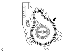
Install a new gasket to the engine water pump assembly.
Note
Clean the surfaces with non-residue solvent before applying seal packing.
-
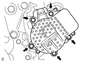
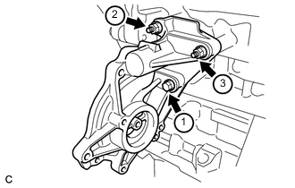
Install the engine water pump assembly with the 5 bolts.
- Torque:
- 21 N*m { 214 kgf*cm, 15 ft.*lbf }
-
-
INSTALL WATER INLET WITH THERMOSTAT SUB-ASSEMBLY
-
Install a new gasket to the water inlet with thermostat sub-assembly.
-
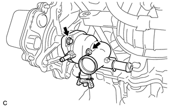
Install the water inlet with thermostat sub-assembly with the 2 bolts.
- Torque:
- 10 N*m { 102 kgf*cm, 7 ft.*lbf }
-
-
INSPECT VALVE CLEARANCE
-
ADJUST VALVE CLEARANCE
-
INSTALL FUEL INJECTOR ASSEMBLY
-
INSTALL INJECTOR VIBRATION INSULATOR
-
INSTALL FUEL DELIVERY SPACER
-
INSTALL FUEL DELIVERY PIPE
-
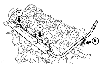
Install the fuel delivery pipe with the 3 bolts.
- Torque:
- Bolt A
- 21 N*m { 214 kgf*cm, 15 ft.*lbf }
- Bolt B
- 10 N*m { 102 kgf*cm, 7 ft.*lbf }
Note
-
Be careful not to drop the fuel injectors when installing the fuel delivery pipe.
-
Check that the fuel injectors rotate smoothly after installing the fuel delivery pipe.
-
-
INSTALL CYLINDER HEAD COVER SUB-ASSEMBLY
-
Install a new gasket to the cylinder head cover sub-assembly.
-
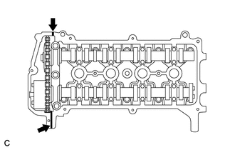
Apply seal packing to the 2 locations shown in the illustration.
Text in Illustration Apply Seal Packing Seal packing Toyota Genuine Seal Packing Black, Three Bond 1207B or equivalent Note
-
Remove any oil from the contact surface.
-
Install the cylinder head cover within 3 minutes of applying seal packing.
-
Do not start the engine for at least 2 hours after installation.
-
-
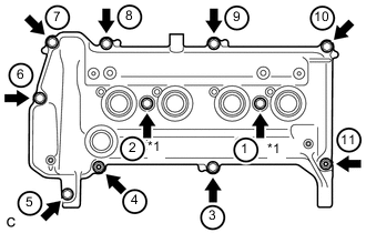
Text in Illustration *1 Seal Washer Temporarily install the cylinder head cover sub-assembly with the 9 bolts, 2 nuts and 2 new seal washers.
-
Using several steps, uniformly tighten the bolts and nuts in the sequence shown in the illustration.
- Torque:
- 13 N*m { 132 kgf*cm, 10 ft.*lbf }
-
-
INSTALL VENTILATION VALVE SUB-ASSEMBLY
-
Apply adhesive to 2 or 3 threads of the ventilation valve sub-assembly.
Adhesive Toyota Genuine Adhesive 1324, Three Bond 1324 or equivalent -
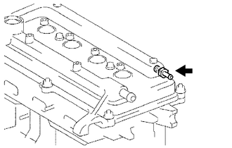
Using a 19 mm deep socket wrench, install the ventilation valve sub-assembly.
- Torque:
- 27 N*m { 275 kgf*cm, 20 ft.*lbf }
-
-
INSTALL ENGINE OIL LEVEL DIPSTICK GUIDE
-
INSTALL OIL FILLER CAP GASKET
-
Install a new oil filler cap gasket to the oil filler cap.
-
-
INSTALL OIL FILLER CAP SUB-ASSEMBLY
-
Install the oil filler cap sub-assembly to the cylinder head cover sub-assembly.
-
-
INSTALL ENGINE OIL PRESSURE SWITCH ASSEMBLY
-
Apply adhesive to 2 or 3 threads of the engine oil pressure switch assembly.
Adhesive Toyota Genuine Adhesive 1344, Three Bond 1344 or equivalent -
Using a 24 mm deep socket wrench, install the engine oil pressure switch assembly.
- Torque:
- 15 N*m { 153 kgf*cm, 11 ft.*lbf }
Note
Do not start the engine within 1 hour of installation.
-
-
INSTALL ENGINE COOLANT TEMPERATURE SENSOR
-
Using a 19 mm union nut wrench, install a new gasket and the engine coolant temperature sensor.
- Torque:
- 20 N*m { 204 kgf*cm, 15 ft.*lbf }
Note
Use the torque value compensation formula to calculate the torque value for use when a torque wrench is combined with a tool such as a union nut wrench Click here.
-
-
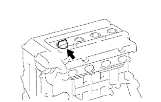
INSTALL KNOCK SENSOR
-
Install the knock sensor with the bolt.
Text in Illustration Up 
Engine Front - Torque:
- 20 N*m { 204 kgf*cm, 15 ft.*lbf }
Note
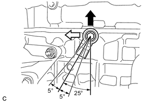
Make sure that the knock control sensor is as shown in the illustration.
-
-
INSTALL O-RING
-
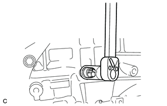
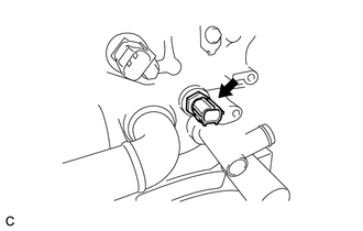
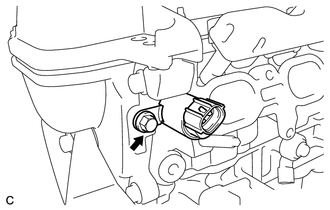
INSTALL CRANKSHAFT POSITION SENSOR
-
INSTALL CAMSHAFT TIMING OIL CONTROL VALVE ASSEMBLY
-
Apply a light coat of engine oil to a new O-ring and install it to the camshaft timing oil control valve assembly.
-
Install the camshaft timing oil control valve assembly with the bolt.
- Torque:
- 7.5 N*m { 76 kgf*cm, 66 in.*lbf }
-
-
INSTALL O-RING
-
INSTALL CAMSHAFT POSITION SENSOR
-
INSTALL SPARK PLUG