ENGINE UNIT DISASSEMBLY

PROCEDURE
-
REMOVE SPARK PLUG
-
REMOVE OIL FILLER CAP SUB-ASSEMBLY
-
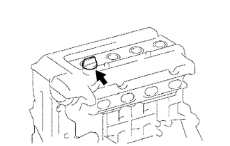
Remove the oil filler cap sub-assembly from the cylinder head cover.
-
-
REMOVE OIL FILLER CAP GASKET
-
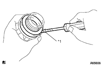
Text in Illustration *1 Protective Tape Using a screwdriver, remove the oil filler cap gasket from the oil filler cap.
Tech Tips
Wrap the screwdriver tip with protective tape before use.
-
-
REMOVE ENGINE OIL LEVEL DIPSTICK GUIDE
-
REMOVE CAMSHAFT POSITION SENSOR
-
REMOVE O-RING
-
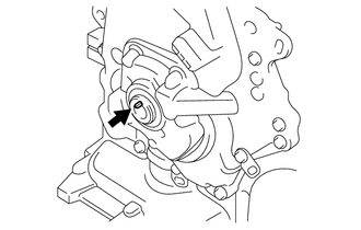
REMOVE CAMSHAFT TIMING OIL CONTROL VALVE ASSEMBLY
-
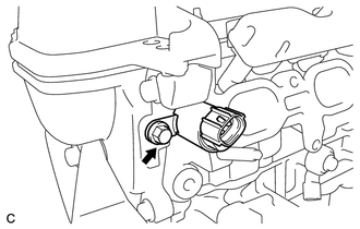
Remove the bolt and camshaft timing oil control valve assembly.
-
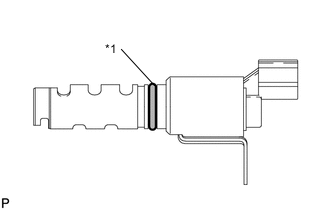
Remove the O-ring from the camshaft timing oil control valve assembly.
-
-
REMOVE KNOCK SENSOR
-
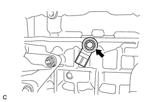
Remove the bolt and knock sensor.
-
-
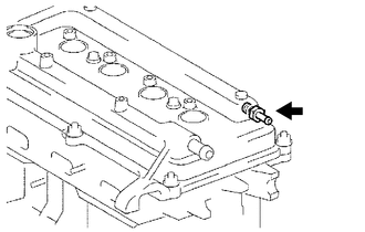
REMOVE ENGINE COOLANT TEMPERATURE SENSOR
-
Using a 19 mm union nut wrench, remove the engine coolant temperature sensor and gasket.
-
-
REMOVE ENGINE OIL PRESSURE SWITCH ASSEMBLY
-
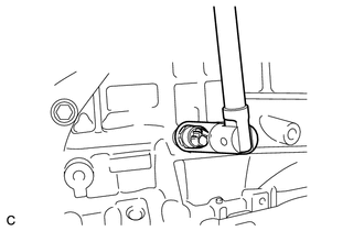
Using a 24 mm deep socket wrench, remove the engine oil pressure switch assembly.
-
-
REMOVE OIL FILTER SUB-ASSEMBLY
-
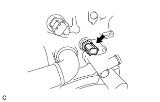
REMOVE CRANKSHAFT POSITION SENSOR
-
REMOVE O-RING
-
REMOVE WATER INLET WITH THERMOSTAT SUB-ASSEMBLY
-
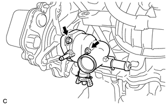
Remove the 2 bolts and water inlet with thermostat sub-assembly.
-
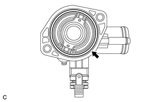
Remove the gasket from the water inlet with thermostat sub-assembly.
-
-
REMOVE ENGINE WATER PUMP ASSEMBLY
-
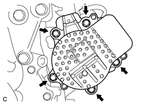
Remove the 5 bolts and engine water pump assembly.
-
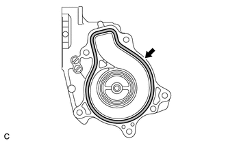
Remove the gasket from the engine water pump assembly.
-
-
REMOVE WATER INLET HOUSING
-
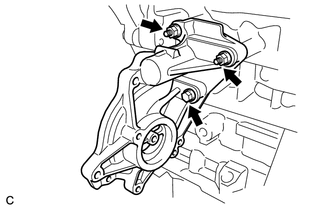
Remove the bolt, 2 nuts and water inlet housing.
-
Remove the gasket.
-
-
REMOVE ENGINE MOUNTING BRACKET RH
-
REMOVE VENTILATION VALVE SUB-ASSEMBLY
-
Using a 19 mm deep socket wrench, remove the ventilation valve sub-assembly from the cylinder head cover sub-assembly.
-
-
REMOVE CYLINDER HEAD COVER SUB-ASSEMBLY
-
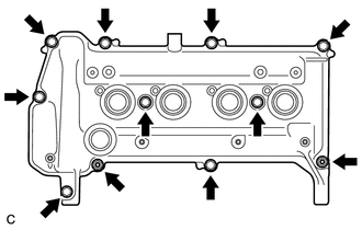
Remove the 9 bolts, 2 seal washers, 2 nuts and cylinder head cover sub-assembly.
-
Remove the gasket from the cylinder head cover sub-assembly.
-
-
REMOVE CRANKSHAFT DAMPER SUB-ASSEMBLY
-
Set the No. 1 cylinder to TDC/compression.
-
Turn the crankshaft damper until its notch and timing mark "0" of the timing chain cover are aligned.
-
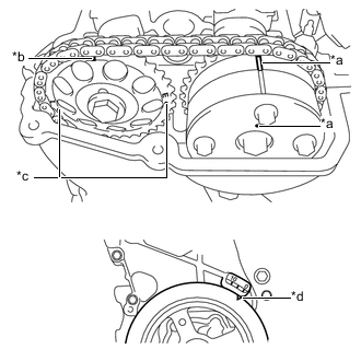
Text in Illustration *a Timing Mark *b Timing Mark (Rectangle) *c Mark (Circle) *d Timing Notch Check that the timing marks on both the camshaft timing sprocket and the camshaft timing gear are facing upward as shown in the illustration.
Tech Tips
-
There are 3 marks on the camshaft timing sprocket. Make sure that the timing mark (rectangle) is at the top.
-
If not, turn the crankshaft 1 complete revolution (360°) and align the marks as above.
-
-
-
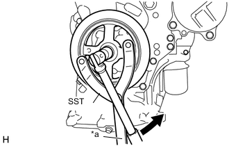
Text in Illustration *a Hold 
Turn Using SST, hold the crankshaft damper sub-assembly in place and loosen the bolt.
- SST
- 09960-10010 ( 09962-01000, 09963-01000 )
Note
When installing SST, be careful that the bolt which holds SST does not interfere with the chain cover.
-
Remove the crankshaft damper sub-assembly and bolt.
-
Remove the crankshaft straight pin.
-
-
REMOVE TIMING CHAIN COVER
-
REMOVE SCREW PLUG
-
REMOVE OIL PUMP SEAL
-
REMOVE NO. 1 CHAIN TENSIONER ASSEMBLY
-
REMOVE CHAIN TENSIONER SLIPPER
-
REMOVE NO. 1 CHAIN VIBRATION DAMPER
-
REMOVE CHAIN SUB-ASSEMBLY
-
REMOVE FUEL DELIVERY PIPE
-
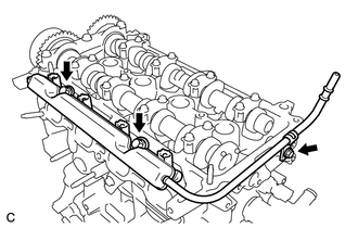
Remove the 3 bolts and fuel delivery pipe.
-
-
REMOVE FUEL DELIVERY SPACER
-
REMOVE INJECTOR VIBRATION INSULATOR
-
REMOVE FUEL INJECTOR ASSEMBLY
-
REMOVE NO. 2 CAMSHAFT
-
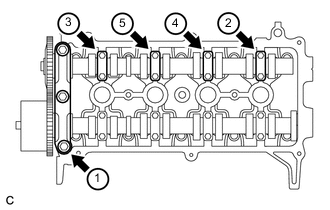
Using several steps, uniformly loosen and remove the 11 bolts in the sequence shown in the illustration. Then remove the No. 1 camshaft bearing cap and 4 No. 2 camshaft bearing caps.
Note
Uniformly loosen the bolts while keeping the No. 2 camshaft level.
-
-
REMOVE CAMSHAFT TIMING GEAR OR SPROCKET
-
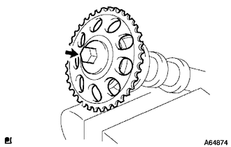
Clamp the No. 2 camshaft in a vise.
Note
Be careful not to damage the No. 2 camshaft.
-
Remove the bolt and camshaft timing gear or sprocket.
-
-
REMOVE CAMSHAFT
-
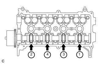
Using several steps, uniformly loosen and remove the 8 bolts in the sequence shown in the illustration. Then remove the 4 No. 2 camshaft bearing caps.
Note
Uniformly loosen the bolts while keeping the camshaft level.
-
-
INSPECT CAMSHAFT TIMING GEAR ASSEMBLY
-
REMOVE CAMSHAFT TIMING GEAR ASSEMBLY
-
REMOVE CYLINDER HEAD SUB-ASSEMBLY
-
REMOVE CYLINDER HEAD GASKET
-
REMOVE OIL FILTER UNION
-
Using a 12 mm hexagon socket wrench, remove the oil filter union.
-
-
REMOVE NO. 2 OIL PAN SUB-ASSEMBLY
-
Remove the oil pan drain plug and gasket.
-
Remove the 9 bolts and 2 nuts.
-
Insert the blade of an oil pan seal cutter between the oil pan and No. 2 oil pan sub-assembly, cut the sealer and remove the No. 2 oil pan sub-assembly.
Note
Be careful not to damage the oil pan and No. 2 oil pan sub-assembly.
-
-
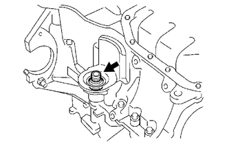
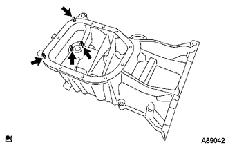
REMOVE OIL STRAINER SUB-ASSEMBLY
-
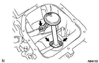
Remove the bolt, 2 nuts, oil strainer sub-assembly and gasket.
-
-
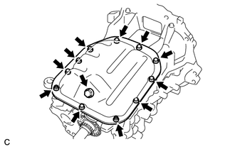
REMOVE OIL PAN SUB-ASSEMBLY
-
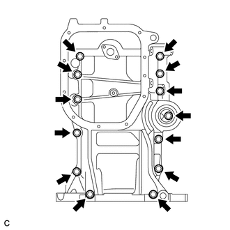
Loosen and remove the 13 bolts uniformly in several steps.
-
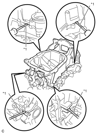
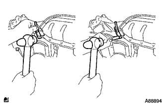
Text in Illustration *1 Protective Tape Using a screwdriver, remove the oil pan sub-assembly by prying between the cylinder block and oil pan sub-assembly.
Note
Be careful not to damage the contact surfaces of the oil pan sub-assembly and cylinder block.
Tech Tips
Wrap the screwdriver tip with protective tape before use.
-
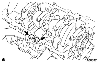
Remove the 2 O-rings from the cylinder block.
-
Using an E5 "TORX" socket wrench, remove the 4 stud bolts.
-
-
REMOVE REAR ENGINE OIL SEAL
-
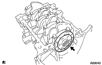
Remove the rear engine oil seal.
-