ENGINE ASSEMBLY INSTALLATION

CAUTION / NOTICE / HINT
CAUTION:
The engine assembly with transaxle is very heavy. Be sure to follow the procedure described in the repair manual, or the engine lifter may suddenly drop.
Tech Tips
Perform "Inspection After Repairs" after replacing the engine assembly, cylinder head sub-assembly camshaft, No. 2 camshaft, camshaft timing gear assembly, piston sub-assembly or piston ring Click here.
PROCEDURE
-
INSTALL NO. 1 ENGINE HANGER
-
INSTALL ENGINE WIRE
-
Connect all of the clamps and connectors and install the engine wire from the engine assembly.
-
-
REMOVE ENGINE STAND
-
Using a chain block and sling device, secure the engine assembly.
Note
-
Make sure that the sling angle is correct to prevent the engine assembly and engine hangers from being damaged or deformed.
-
Securely support the engine assembly to prevent it from turning upside down until it is secured to an engine stand.
-
-
Remove the engine stand from the engine.
-
-
INSTALL ENGINE MOUNTING INSULATOR LH
Tech Tips
Perform this procedure only when replacement of the engine mounting insulator LH is necessary.
-
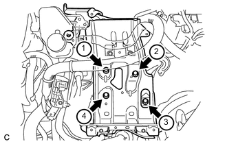
Temporarily install the engine mounting insulator LH with the 5 bolts.
-
Tighten the 5 bolts in the sequence shown in the illustration.
- Torque:
- 52 N*m { 530 kgf*cm, 38 ft.*lbf }
-
Connect the wire harness clamp.
-
-
INSTALL ENGINE MOUNTING INSULATOR SUB-ASSEMBLY RH
Tech Tips
Perform this procedure only when replacement of the engine mounting insulator sub-assembly RH is necessary.
-
Temporarily install the engine mounting insulator sub-assembly RH with the 3 bolts.
-
Tighten the 3 bolts in the sequence shown in the illustration.
- Torque:
- 52 N*m { 530 kgf*cm, 38 ft.*lbf }
-
-
INSTALL FLYWHEEL SUB-ASSEMBLY
-
Gently place the engine assembly onto wood blocks or equivalent.
Note
-
Set the engine assembly so that it is level.
-
To prevent the No. 2 oil pan sub-assembly from deforming, do not place any attachments onto the No. 2 oil pan sub-assembly of the engine assembly.
-
This step should be done while hanging the engine assembly using the sling device and chain block.
-
-
Install the flywheel sub-assembly Click here.
-
-
INSTALL TRANSMISSION INPUT DAMPER ASSEMBLY
-
Gently place the engine assembly onto wood blocks or equivalent.
Note
-
Set the engine assembly so that it is level.
-
To prevent the No. 2 oil pan sub-assembly from deforming, do not place any attachments onto the No. 2 oil pan sub-assembly of the engine assembly.
-
This step should be done while hanging the engine assembly using the sling device and chain block.
-
-
Install the transmission input damper assembly Click here.
-
-
INSTALL ENGINE ASSEMBLY
-
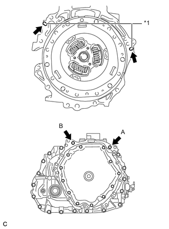
Text in Illustration *1 Knock Pin Make sure that the knock pins are installed to the engine.
-
Temporarily install the hybrid vehicle transaxle assembly to the engine with the 2 bolts.
Tech Tips
Temporarily tighten bolt B first.
-
Fully tighten the 2 bolts in the order of A and B.
- Torque:
- 64 N*m { 653 kgf*cm, 47 ft.*lbf }
Note
-
Make sure that the wire harness or similar items are not pinched between the contact surfaces.
-
Do not forcibly pry on the hybrid vehicle transaxle.
-
Make sure to align the hybrid vehicle transaxle so that the input shaft of the hybrid vehicle transaxle will be inserted straight into the inner splines of the transmission input damper assembly.
-
Do not apply grease either to the inner splines of the transmission input damper assembly or to the outer splines of the input shaft.
-
When inserting the input shaft of the hybrid vehicle transaxle into the inner splines of the transmission input damper, do not shake the hybrid vehicle transaxle excessively.
-
When mounting the hybrid vehicle transaxle to the engine, make sure to securely fit the knock pins into the knock holes.
-
When tightening the bolts, be sure that the mating surfaces of the engine and the hybrid vehicle transaxle assembly are in close contact with one another.
Bolt Length 45 mm (1.77 in.) -
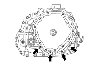
Install the 4 bolts.
- Torque:
- 30 N*m { 301 kgf*cm, 22 ft.*lbf }
Bolt Length 45 mm (1.77 in.) -
Engage the claw and install the flywheel housing side cover to the engine.
-
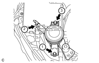
Install the starter hole heat insulator to the engine with the 2 bolts.
- Torque:
- 30 N*m { 301 kgf*cm, 22 ft.*lbf }
Bolt Length 45 mm (1.77 in.) -
Install the drive shaft heat insulator bracket to the engine with the 2 bolts.
- Torque:
- 30 N*m { 301 kgf*cm, 22 ft.*lbf }
Bolt Length 45 mm (1.77 in.) -
Connect the clamp to the drive shaft heat insulator bracket.
-
Install the drive shaft heat insulator sub-assembly to the engine and drive shaft heat insulator bracket with the bolt and nut.
- Torque:
- 18 N*m { 179 kgf*cm, 13 ft.*lbf }
-
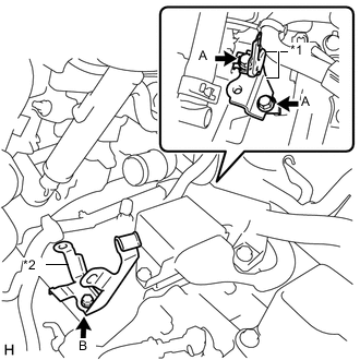
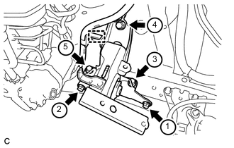
Text in Illustration *1 Wire Harness Clamp Bracket *2 Transmission Control Cable Clamp Install the 2 wire harness clamp brackets and transmission control cable clamp to the hybrid vehicle transaxle assembly with the 3 bolts.
- Torque:
- Bolt A
- 13 N*m { 130 kgf*cm, 9 ft.*lbf }
- Bolt B
- 12 N*m { 122 kgf*cm, 9 ft.*lbf }
-
Connect the 7 clamps, 4 connectors and install the wire harness to the hybrid vehicle transaxle assembly with the 3 bolts.
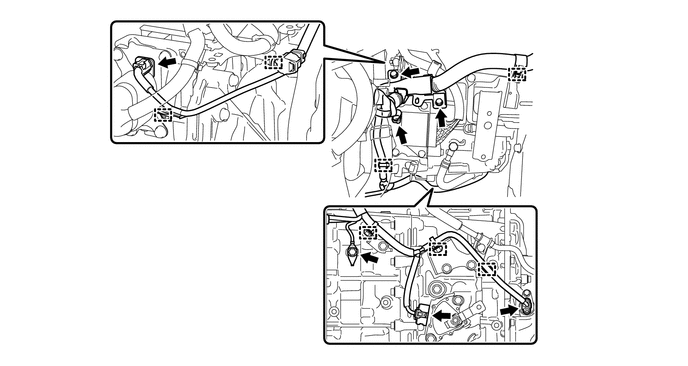
- Torque:
- 13 N*m { 130 kgf*cm, 9 ft.*lbf }
-
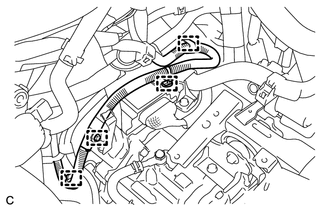
Connect the 4 clamps and No. 2 engine wire.
-
-
INSTALL ENGINE ASSEMBLY WITH TRANSAXLE
-
Using a sling device and chain block, set the engine assembly with transaxle on the engine lifter.
Note
-
Place the height adjustment attachment and plate lift attachment so that the engine assembly with transaxle is level.
-
Securely support the engine assembly to prevent it from turning upside down until it is secured to an engine stand.
-
To prevent the No. 2 oil pan sub-assembly from deforming, do not place any attachments onto the No. 2 oil pan sub-assembly of the engine assembly.
-
Do not place any attachments onto the drain plug and rear cover plug of the hybrid vehicle transaxle assembly.
-
Make sure to support the engine assembly with transaxle securely to prevent it from falling.
-
-
Remove the 2 bolts and 2 No. 1 engine hangers.
-
Operate the engine lifter and lift the engine assembly with transaxle and front suspension crossmember to the position where the engine mounting insulator sub-assembly RH and engine mounting insulator LH can be installed.
CAUTION:
Do not raise the engine more than necessary. If the engine is raised excessively, the vehicle may also be lifted up.
Note
Make sure that the engine is clear of all wiring and hoses.
-
Operate the engine lifter and lift the engine assembly with transaxle and front suspension crossmember to the position where the front suspension crossmember can be installed.
-
By inserting SST into the datum holes in the front suspension crossmember RH and LH alternately, temporarily install the front suspension crossmember with the 6 bolts.
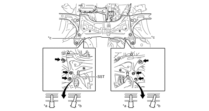
Text in Illustration *a CORRECT *b INCORRECT *c Datum Hole - - - SST
- 09670-00010
-
Connect the engine mounting insulator LH with the bolt and nut to the engine assembly.
- Torque:
- 52 N*m { 530 kgf*cm, 38 ft.*lbf }
-
Connect the engine mounting insulator sub-assembly RH with the bolt and 2 nuts to the engine assembly.
- Torque:
- 52 N*m { 530 kgf*cm, 38 ft.*lbf }
-
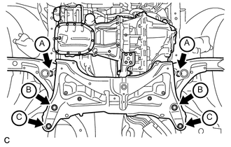
Using several steps, uniformly tighten the 6 bolts.
- Torque:
- Bolt A
- 87 N*m { 887 kgf*cm, 64 ft.*lbf }
- Bolt B
- 151 N*m { 1539 kgf*cm, 111 ft.*lbf }
- Bolt C
- 98 N*m { 999 kgf*cm, 72 ft.*lbf }
-
-
INSTALL FLYWHEEL HOUSING UNDER COVER
-
Install the flywheel housing under cover.
-
-
INSTALL FRONT DRIVE SHAFT ASSEMBLY
-
INSTALL NO. 2 ENGINE ROOM RELAY BLOCK AND NO. 2 JUNCTION BLOCK ASSEMBLY
-
INSTALL FRONT EXHAUST PIPE ASSEMBLY
-
INSTALL FRONT FLOOR CENTER BRACE
-
INSTALL COMPRESSOR WITH MOTOR ASSEMBLY
-
CONNECT SUCTION HOSE SUB-ASSEMBLY
-
CONNECT NO. 1 COOLER REFRIGERANT DISCHARGE HOSE
-
INSTALL NO. 1 STEERING COLUMN HOLE COVER SUB-ASSEMBLY
-
CONNECT STEERING INTERMEDIATE SHAFT ASSEMBLY
-
INSTALL COLUMN HOLE COVER SILENCER SHEET
-
CONNECT TRANSMISSION CONTROL CABLE ASSEMBLY
-
CONNECT ENGINE WIRE (for RHD)
-
Connect the wire harness clamp.
-
Connect the engine wire to the engine room main wire.
-
Connect the engine wire to the engine room relay block and junction block assembly and engage the claw.
-
Connect the 2 wire harness clamps and 2 connectors.
-
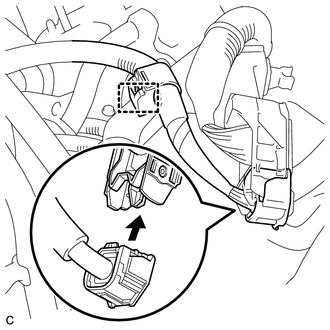
Connect the ECM connector and lower the lever.
Note
-
When connecting the connector, make sure that dirt, water or other foreign matter does not become stuck between the connector and other part.
-
Make sure that the lever is securely locked.
-
-
-
CONNECT ENGINE WIRE (for LHD)
-
Connect the wire harness clamp.
-
Connect the engine wire to the engine room main wire.
-
Connect the engine wire to the engine room relay block and junction block assembly and engage the claw.
-
Connect the 2 wire harness clamps and 2 connectors.
-
Connect the 2 wire harness clamps.
-
Connect the ECM connector and lower the lever.
Note
-
When connecting the connector, make sure that dirt, water or other foreign matter does not become stuck between the connector and other part.
-
Make sure that the lever is securely locked.
-
-
-
CONNECT FUEL TUBE SUB-ASSEMBLY
-
INSTALL EFI FUEL PIPE CLAMP
-
INSTALL NO. 1 FUEL VAPOR FEED HOSE
-
Connect the 2 hose clamps and install the No. 1 fuel vapor feed hose.
-
-
CONNECT HEATER WATER HOSE
-
Connect the 2 heater water hoses.
-
-
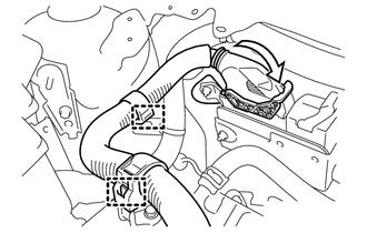
CONNECT NO. 2 RADIATOR HOSE
-
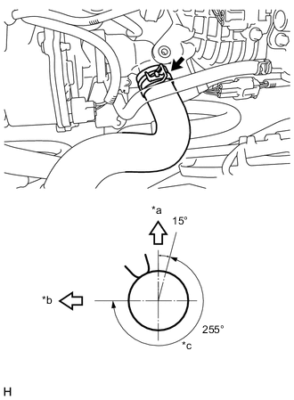
Text in Illustration *a Up *b for LH Side *c Do Not Position Hose Clamp Claws In This Area Connect the No. 2 radiator hose.
Tech Tips
Make sure that the claws on the hose clamp are positioned as shown in the illustration.
-
-
CONNECT NO. 1 RADIATOR HOSE
-
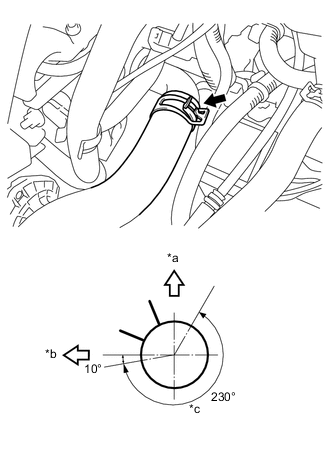
Text in Illustration *a Up *b for LH Side *c Do Not Position Hose Clamp Claws In This Area Connect the No. 1 radiator hose.
Tech Tips
Make sure that the claws on the hose clamp are positioned as shown in the illustration.
-
-
INSTALL INVERTER BRACKET ASSEMBLY
CAUTION:
Wear insulated gloves.
-
Temporarily install the inverter bracket assembly with the 4 bolts.
-
Tighten the 4 bolts in the sequence shown in the illustration.
- Torque:
- 21 N*m { 214 kgf*cm, 15 ft.*lbf }
-
Connect the ground wire with the bolt.
- Torque:
- 8.4 N*m { 85 kgf*cm, 74 in.*lbf }
-
Install the inverter reservoir tank assembly with the 2 bolts.
- Torque:
- 7.0 N*m { 71 kgf*cm, 62 in.*lbf }
-
Connect the 2 wire harness clamps.
-
Connect the motor cable protector with the bolt.
- Torque:
- 8.0 N*m { 82 kgf*cm, 71 in.*lbf }
-
-
INSTALL AIR CLEANER CASE SUB-ASSEMBLY
-
INSTALL AIR CLEANER CAP SUB-ASSEMBLY
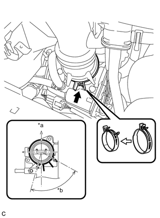
Text in Illustration *a Engine Side *b 75°
-
Install the air cleaner hose sub-assembly and lock the hose clamp.
Note
-
Align the groove of the air cleaner hose with the tab of the throttle body with motor assembly and install the hose.
-
Make sure that the tab of the air cleaner hose clamp stays within the range shown by *b.
-
-
Install the air cleaner cap sub-assembly with the 2 clamps.
-
Connect the wire harness clamp and mass air flow meter connector.
-
Connect the No. 1 fuel vapor feed hose and No. 2 fuel vapor feed hose.
-
Connect the purge VSV connector and wire harness clamp.
-
Connect the hose clamp and ventilation hose.
-
-
INSTALL INVERTER WITH CONVERTER ASSEMBLY
-
INSTALL OUTER COWL TOP PANEL (for LHD)
-
INSTALL OUTER COWL TOP PANEL (for RHD)
-
INSTALL INNER COWL TOP TO COWL BRACE (for LHD)
-
INSTALL INNER COWL TOP TO COWL BRACE (for RHD)
-
INSTALL FRONT NO. 1 VENTILATOR SEAL (for LHD)
-
INSTALL FRONT NO. 1 VENTILATOR SEAL (for RHD)
-
INSTALL FRONT AIR SHUTTER SEAL RH (for LHD)
-
INSTALL FRONT AIR SHUTTER SEAL RH (for RHD)
-
INSTALL WINDSHIELD WIPER MOTOR AND LINK ASSEMBLY
-
ADD COOLANT (for Engine)
-
ADD COOLANT (for Inverter)
-
ADD HYBRID TRANSAXLE FLUID
-
INSPECT HYBRID TRANSAXLE FLUID
-
ADD ENGINE OIL
-
CONNECT CABLE TO NEGATIVE AUXILIARY BATTERY TERMINAL
-
INSTALL SERVICE PLUG GRIP
-
CHARGE AIR CONDITIONING SYSTEM WITH REFRIGERANT
-
WARM UP COMPRESSOR
-
INSPECT FOR REFRIGERANT LEAK
-
CHECK ENGINE OIL LEVEL
-
INSPECT FOR FUEL LEAK
-
INSPECT FOR COOLANT LEAK (for Engine)
-
INSPECT FOR COOLANT LEAK (for Inverter)
-
INSPECT FOR HYBRID TRANSAXLE FLUID LEAK
-
INSPECT FOR OIL LEAK
-
INSPECT FOR EXHAUST GAS LEAK
-
INSPECT IGNITION TIMING
-
INSPECT ENGINE IDLE SPEED
-
INSPECT CO/HC
-
INSPECT SHIFT LEVER POSITION
-
ADJUST SHIFT LEVER POSITION
-
INSPECT AND ADJUST FRONT WHEEL ALIGNMENT
-
CHECK ABS SPEED SENSOR SIGNAL
-
INSTALL NO. 2 CYLINDER HEAD COVER (w/ No. 2 Cylinder Head Cover)
-
INSTALL ENGINE UNDER COVER RH
- Torque:
- 5.0 N*m { 51 kgf*cm, 44 in.*lbf }
-
INSTALL ENGINE UNDER COVER LH
- Torque:
- 5.0 N*m { 51 kgf*cm, 44 in.*lbf }