INVERTER CURRENT SENSOR REASSEMBLY
CAUTION / NOTICE / HINT
Tech Tips
For the assembly procedure of the inverter with converter assembly, refer to the assembly procedure of the MG control computer with bracket sub-assembly Click here.
PROCEDURE
-
INSTALL INVERTER CURRENT SENSOR SUB-ASSEMBLY
-
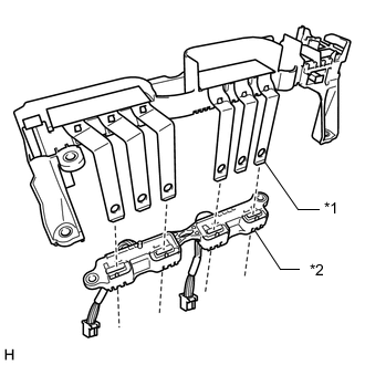
Text in Illustration *1 Bus-bar *2 Inverter current sensor sub-assembly Insert the bus-bars of the inverter terminal sub-assembly into the inverter current sensor sub-assembly as shown in the illustration.
-
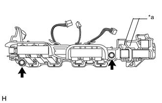
Text in Illustration *a Terminal Tray Install the inverter current sensor sub-assembly with the 2 bolts.
- Torque:
- 5.0 N*m { 51 kgf*cm, 44 in.*lbf }
-
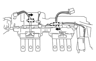
Engage the wire harness of inverter current sensor sub-assembly to the 2 clamps as shown in the illustration.
-
Remove the protective tape.
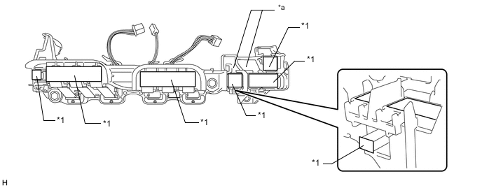
Text in Illustration *1 Protective Tape - - *a Terminal Tray - -
-