INVERTER CURRENT SENSOR DISASSEMBLY
CAUTION / NOTICE / HINT
Tech Tips
For the disassembly procedure of the inverter with converter assembly, refer to the disassembly procedure of the MG control computer with bracket sub-assembly Click here.
PROCEDURE
-
REMOVE INVERTER CURRENT SENSOR SUB-ASSEMBLY
-
Apply protective tape to the inverter terminal with sensor sub-assembly as shown in the illustration.
Note
Use non-residue type tape.
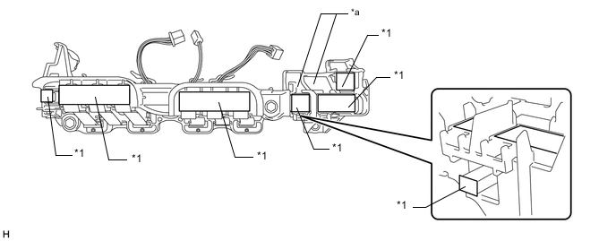
Text in Illustration *1 Protective Tape - - *a Terminal Tray - - -
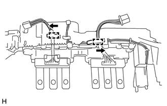
Disengage the 2 wire harnesses of the inverter current sensor sub-assembly from each clamp as shown in the illustration.
-
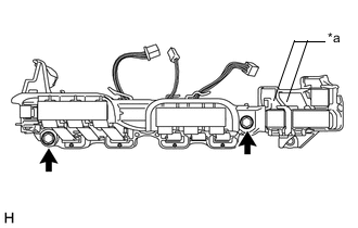
Text in Illustration *a Terminal Tray Remove the 2 bolts and inverter current sensor sub-assembly.
Note
Do not touch the bus-bars.
-