ELECTRIC VEHICLE CONVERTER DISASSEMBLY

CAUTION / NOTICE / HINT
Note
If metal shavings are created when bolts are removed from the inverter with converter assembly, remove them using tape or equivalent.
Tech Tips
Prepare 2 tubes of thermal grease X-23-7884-4 when replacing the hybrid vehicle converter kit.
-
For Europe : 08887-83080
-
For except Europe : 08887-02809
PROCEDURE
-
REMOVE INVERTER WITH CONVERTER ASSEMBLY
-
DRAIN COOLANT (for Inverter)
CAUTION:
Wear insulating gloves.
-
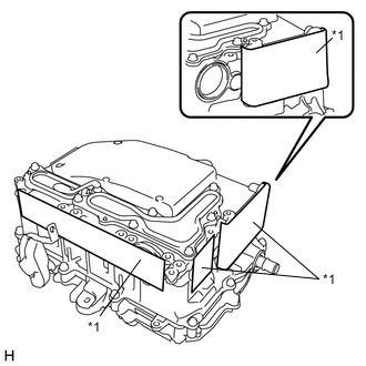
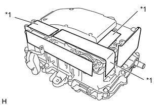
Text in Illustration *1 Protective Tape Apply protective tape to the areas shown in the illustration without leaving any gaps between the tape and part.
Note
Use non-residue type tape.
-
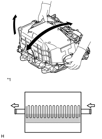
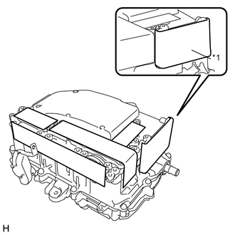
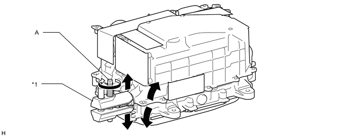
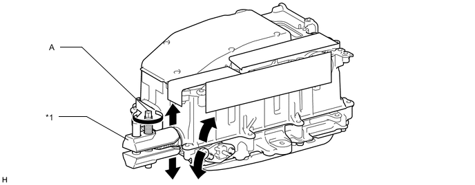
Text in Illustration *1 Coolant (for inverter) Passage Tilt the inverter with converter assembly back and forth to drain the coolant (for inverter).
Note
Do not hold the inverter with converter assembly by the coolant pipes or inverter signal connector.
Tech Tips
The coolant (for inverter) passage is designed as shown in the illustration. Tilt the inverter with converter assembly back and forth repeatedly to drain the coolant (for inverter) completely.
-
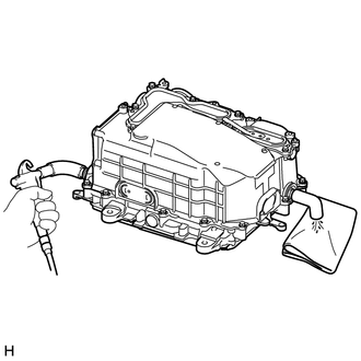
Blow compressed air into the inverter with converter assembly until most all of the coolant (for inverter) is blown out.
Note
Do not damage the coolant pipes.
Tech Tips
-
Use a piece of cloth as shown in the illustration to prevent the coolant (for inverter) from spraying.
-
Cover the air inlet port with a piece of cloth to minimize air leakage.
-
-
-
CLEAN INVERTER WITH CONVERTER ASSEMBLY
CAUTION:
Wear insulating gloves.
-
Using a piece of cloth, clean the outside of the inverter with converter assembly and around the bolts.
Note
To prevent foreign matter from entering the inverter with converter assembly, make sure that the protective tape is not partially removed.
-
Turn the inverter with converter assembly over and clean around the bolts.
Note
Do not hold the inverter with converter assembly by the coolant pipes.
-
-
REMOVE INVERTER TERMINAL COVER
CAUTION:
Wear insulated gloves.
-
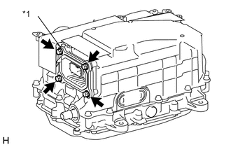
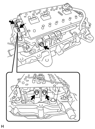
Text in Illustration *1 Interlock Connector Remove the 2 bolts and inverter terminal cover.
CAUTION:
An interlock connector is installed to the inverter terminal cover. Make sure to remove the inverter terminal cover before removing the inverter cover.
Note
Make sure to pull the inverter terminal cover straight up, as a connector is connected to the bottom of the cover.
-
-
REMOVE INVERTER COVER
CAUTION:
Wear insulating gloves.
-
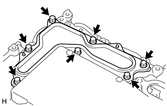
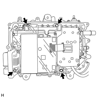
Remove the 7 bolts and inverter cover.
Note
An interlock connector is installed to the inverter terminal cover. Make sure to remove the inverter terminal cover before removing the inverter cover.
-
-
REMOVE INVERTER SIGNAL CONNECTOR COVER
CAUTION:
Wear insulating gloves.
-
Text in Illustration *1 Protective Tape Apply protective tape to the area that was exposed when the inverter terminal cover was removed.
Note
Use non-residue type tape.
-
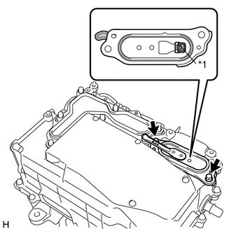
Text in Illustration *1 Protective Tape Remove the protective tape from the inverter signal connector.
-
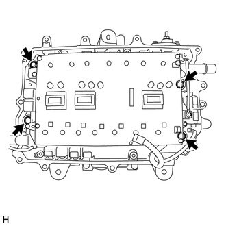
Text in Illustration *1 Inverter Signal Connector Cover Remove the 4 bolts and inverter signal connector cover.
Tech Tips
As there will be dust and dirt around the inverter signal connector cover gasket, before removing the inverter signal connector cover, clean the area around the inverter signal connector cover with a piece of cloth to prevent foreign matter from entering the inverter with converter assembly.
-
-
REMOVE NO. 1 AND NO. 2 INVERTER DRAIN PLUG
CAUTION:
-
Wear insulating gloves.
-
Wear protective goggles.
-
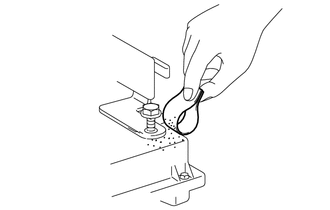
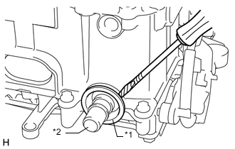
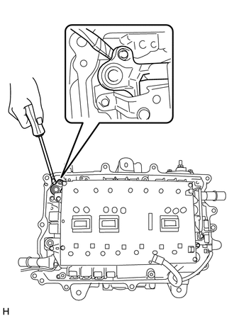
Text in Illustration *1 No. 1 Inverter Drain Plug *2 No. 2 Inverter Drain Plug Using a screwdriver with its tip wrapped with protective tape, remove the No. 1 and No. 2 inverter drain plugs.
Note
-
Do not damage the sealing surfaces of the inverter with converter assembly.
-
Do not touch or allow grease or oil to contact the sealing surfaces of the inverter case with condenser.
-
-
-
VERIFY THAT VOLTAGE OF INVERTER WITH CONVERTER IS 0 V
CAUTION:
Wear insulating gloves.
Note
Do not allow any foreign matter or water to enter the inverter with converter assembly.
-
Using a voltmeter, measure the voltage between the high voltage cable connector terminals.
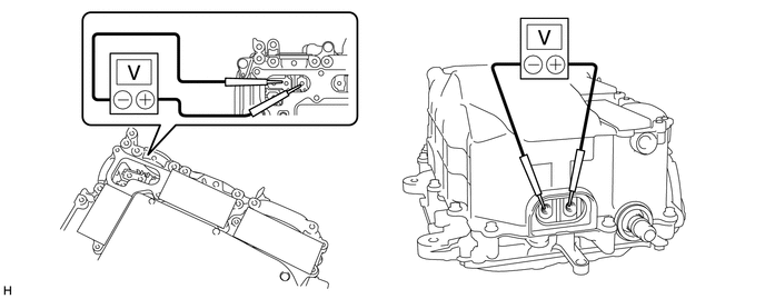
Standard voltage 0V Tech Tips
Use measuring range of DC 750 V or more on the voltmeter.
-
-
REMOVE INVERTER UNION GROMMET
-
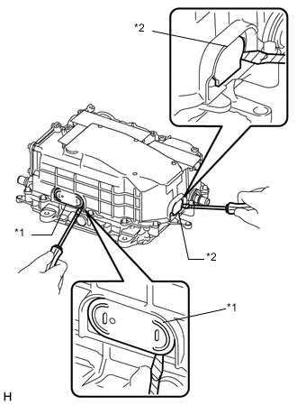
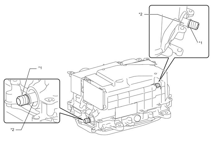
Text in Illustration *1 Inverter Union Grommet *2 Coolant Pipe Using a screwdriver with its tip wrapped with protective tape, remove the 2 inverter union grommets from the inverter with converter assembly.
Note
Pull the grommet straight out without applying any force to the coolant pipes.
-
-
REMOVE NO. 2 ENGINE ROOM WIRE
-
Disengage the 2 claws and open the terminal cover.
-
Remove the nut.
-
Disengage the clamp and remove the No. 2 engine room wire from the inverter with converter assembly.
-
-
REMOVE INVERTER CASE WITH CONDENSER
-
Remove the 5 bolts.
Note
Do not touch the bus-bars.
-
Text in Illustration *1 Protective Tape Apply protective tape to the installation holes of the No. 1 and No. 2 inverter drain plugs as shown in the illustration.
Note
-
Use non-residue type tape.
-
Do not touch or allow grease or oil to contact the sealing surfaces of the inverter case with condenser.
-
-
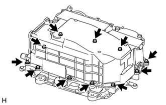
Remove the 11 bolts.
-
Apply protective tape to the coolant pipe as shown in the illustration.
Text in Illustration *1 Protective Tape *2 Coolant Pipe Note
-
Do not apply excessive force to the coolant pipe.
-
Do not damage the coolant pipe.
-
Use non-residue type tape.
-
-
Install SST to the inverter with converter assembly. (Step A)
- SST
- 09891-47020
-
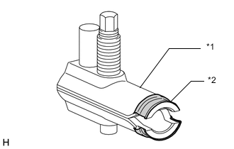
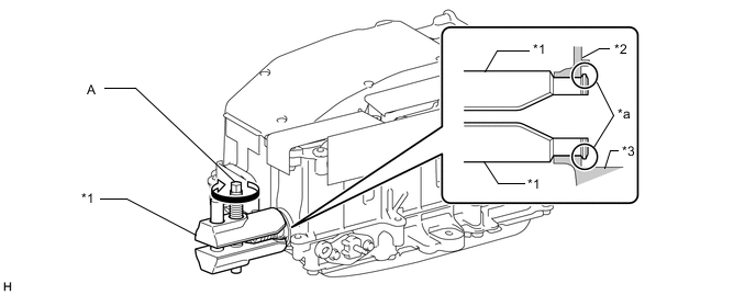
Text in Illustration *1 SST *2 Protective Tape Apply protective tape to SST as shown in the illustration.
-
Insert SST into the inverter union grommet installation hole and tighten the bolt (A) of SST to install SST to the inverter with converter assembly as shown in the illustration.
Text in Illustration *1 SST *2 Inverter Case with Condenser *3 Hybrid Vehicle Converter Kit - - *a Tip - - Note
-
Do not damage the grommet sealing surface of the inverter with converter assembly.
-
Do not apply excessive force to the coolant pipe.
-
-
Check that the tips of SST are not in contact with the grommet sealing surface of the inverter with converter assembly.
-
While supporting SST by hand, tighten the bolt A of SST to separate the inverter case with condenser and hybrid vehicle converter kit as shown in the illustration. (Step B)
Text in Illustration *1 SST - - Note
Do not use air tools.
-
Remove SST from the inverter with converter assembly, and then insert SST into the inverter union grommet installation hole on the opposite side of the inverter with converter assembly and tighten the bolt (A) of SST to install SST to the inverter with converter assembly as shown in the illustration. (Step C)
Text in Illustration *1 SST *2 Inverter Case with Condenser *3 Hybrid Vehicle Converter Kit - - *a Tips - - -
While supporting SST by hand, tighten the bolt A of SST to separate the inverter case with condenser and hybrid vehicle converter kit as shown in the illustration. (Step D)
Text in Illustration *1 SST - - Note
Do not use air tools.
-
Perform steps A, B, C and D on the opposite side of the inverter with converter assembly and remove the inverter case with condenser from the hybrid vehicle converter kit.
-
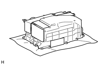
Place the inverter case with condenser on a clean piece of cloth.
Note
-
Do not touch the bus-bars.
-
Do not touch or allow grease or oil to contact the sealing surfaces of the inverter case with condenser.
-
-
-
HOW TO PREVENT STATIC ELECTRICITY
- SST
- 09890-47010
Note
-
Static electricity should be eliminated when removing/installing the inverter with converter assembly.
-
Do not touch the electronic components of a circuit board.
-
Keep clothes away from electronic components.
-
Place parts removed from the inverter with converter assembly on an antistatic mat.
-
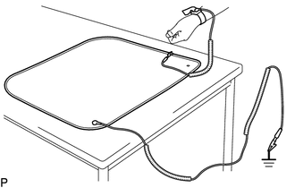
Wear an antistatic wrist strap.
-
Connect the ground clip of the antistatic mat securely to a ground point provided in the workshop or on a workbench (anchor bolt).
Tech Tips
If the ground clip cable is too short, use an extension cable.
-
Connect the ground clip of the antistatic wrist strap securely to the specified point of the antistatic mat.
-
After removing the inverter case with condenser, perform work with bare hands to prevent damage from static electricity and entry of foreign matter.
-
REMOVE INVERTER TERMINAL WITH SENSOR SUB-ASSEMBLY
Note
-
If metal shavings are created, remove them using tape or equivalent.
-
Do not touch the circuit board.
-
Do not allow any moisture to come into contact with the inverter terminal with sensor sub-assembly.
-
Do not touch or allow grease or oil to contact the sealing surfaces of the inverter case with condenser.
-
Disconnect the 3 connectors from the MG control computer with bracket sub-assembly.
Note
Do not move a pen sheet out of position when disconnecting the connectors.
Tech Tips
-
If the pen sheet is moved out of position, return it to its original position when connecting the connectors.
-
-
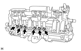
Remove the 6 bolts.
Note
Do not touch the bus-bars.
-
Remove the 4 bolts and inverter terminal with sensor sub-assembly.
-
-
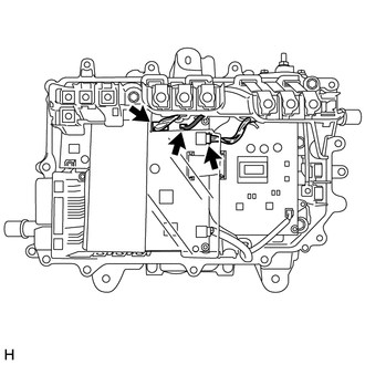
REMOVE MG CONTROL COMPUTER WITH BRACKET SUB-ASSEMBLY
Note
-
If metal shavings are created, remove them using tape or equivalent.
-
Do not touch the circuit board.
-
Do not allow any moisture to come into contact with the MG control computer with bracket sub-assembly.
-
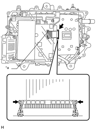
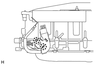
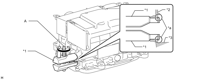
Text in Illustration *a Do not disconnect While disengaging the white resin lock claws of the connector, disconnect the flat cable from the power module intelligent transistor kit.
Note
-
Do not disconnect the flat cable from the MG control computer with bracket sub-assembly.
-
Do not use any tools.
-
-
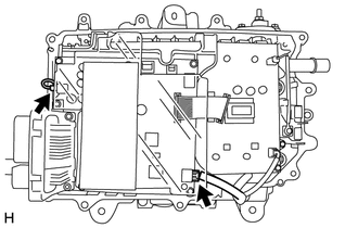
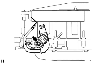
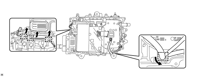
Disconnect the 2 connectors.
Note
Do not move a pen sheet out of position when disconnecting the connectors.
-
Disconnect the connector.
-
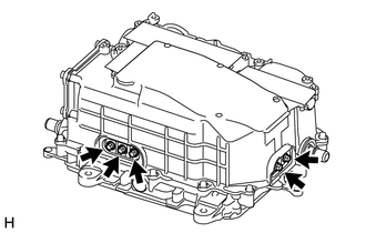
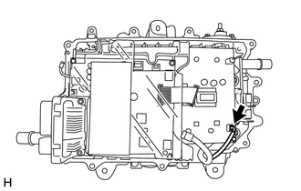
Disengage the 2 wire harnesses from the 4 clamps.
-
Remove the 4 bolts and MG control computer with bracket sub-assembly.
-
-
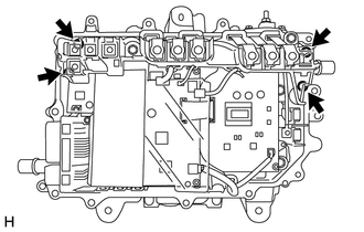
REMOVE POWER MODULE INTELLIGENT TRANSISTOR KIT
Note
-
If metal shavings are created, remove them using tape or equivalent.
-
Do not touch the circuit board.
-
Do not allow any moisture to come into contact with the power module intelligent transistor kit.
-
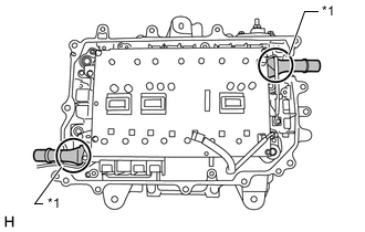
Remove the 3 bolts.
Note
Do not touch the bus-bars.
-
Remove the 4 bolts.
-
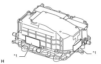
Using a screwdriver with its tip wrapped with protective tape, lift the power module intelligent transistor kit.
-
Text in Illustration *1 Base of the coolant pipe While holding the base of the coolant pipes, remove the power module intelligent transistor kit.
Note
Do not touch the circuit board.
-