INVERTER WITH CONVERTER INSTALLATION
PROCEDURE
-
INSTALL HIGH VOLTAGE FUSE
CAUTION:
Wear insulated gloves.
Tech Tips
Perform this procedure only when replacement of the high voltage fuse is necessary.
-

Text in Illustration *1 Interlock Connector Remove the 2 bolts and inverter terminal cover.
Note
Make sure to pull the inverter terminal cover straight up to remove it, because an interlock connector is connected to the bottom of the inverter terminal cover.
-
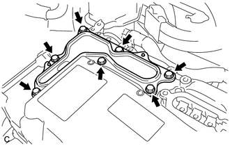
Remove the 7 bolts and inverter cover.
-
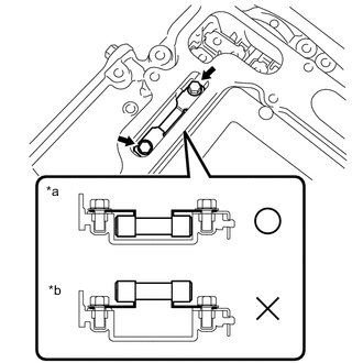
Text in Illustration *a Correct *b Incorrect Install the high voltage fuse with the 2 bolts.
- Torque:
- 5.0 N*m { 51 kgf*cm, 44 in.*lbf }
Note
-
Be sure to use a torque wrench to tighten the bolts.
-
The fuse should be installed with its orientation as shown in the illustration.
-
Temporarily install the inverter cover with the 7 bolts to prevent any foreign matter or water from entering the inverter with converter assembly.
-
Text in Illustration *1 Interlock Connector Temporarily install the inverter terminal cover with the 2 bolts to prevent any foreign matter or water from entering the inverter with converter assembly.
Note
Make sure that the interlock connector is fully engaged.
-
-
INSTALL INVERTER WITH CONVERTER ASSEMBLY
CAUTION:
Wear insulated gloves.
-
Temporarily install the inverter with converter assembly with the 3 bolts.
Note
-
Since the inverter with converter assembly is very heavy, 2 people are needed to install the inverter with converter assembly. When installing the inverter with converter assembly, do not damage the parts around it.
-
To prevent damage, do not hold the inverter with converter assembly by the connectors.
-
To prevent damage due to static electricity, do not touch the terminals of the disconnected connectors.
-
-
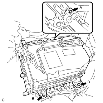
Tighten bolt A.
- Torque:
- 12 N*m { 122 kgf*cm, 9 ft.*lbf }
-
Tighten the 2 bolts B.
- Torque:
- 12 N*m { 122 kgf*cm, 9 ft.*lbf }
-
-
CONNECT NO. 1 INVERTER COOLING HOSE ASSEMBLY
-
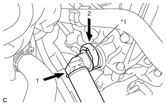
Text in Illustration *1 Retainer Connect the No. 1 inverter cooling hose assembly to the inverter with converter assembly and lock the hose with the retainer.
Note
-
Insert the retainer until a click sound is heard.
-
Pull on the hose to confirm that the hose is securely connected.
-
If there is foreign matter on the union or the O-ring, clean it with water and finger scouring.
-
To prevent foreign matter from entering the cooling system, do not remove the pieces of cloth or plastic bags from the pipe and disconnected hose until installation.
-
-
-
CONNECT NO. 2 INVERTER COOLING HOSE ASSEMBLY
-
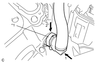
Text in Illustration *1 Retainer Connect the No. 2 inverter cooling hose assembly to the inverter with converter assembly and lock the hose with the retainer.
Note
-
Insert the retainer until a click sound is heard.
-
Pull on the hose to confirm that the hose is securely connected.
-
If there is foreign matter on the union or the O-ring, clean it with water and finger scouring.
-
To prevent foreign matter from entering the cooling system, do not remove the pieces of cloth or plastic bags from the pipe and disconnected hose until installation.
-
-
-
CONNECT WIRE HARNESS
-
Disconnect the wire harness from the protector.
-
Engage the 2 claws and connect the wire harness to the relay block.
-
Install the nut.
- Torque:
- 8.4 N*m { 86 kgf*cm, 74 in.*lbf }
-
Engage the 2 claws and install the No. 1 relay block cover.
-
Connect the connector.
-
Install the relay block cover.
-
-
REMOVE INVERTER TERMINAL COVER
CAUTION:
Wear insulated gloves.
-
Text in Illustration *1 Interlock Connector Remove the 2 bolts and inverter terminal cover.
Note
Make sure to pull the inverter terminal cover straight up to remove it, because an interlock connector is connected to the bottom of the inverter terminal cover.
-
-
REMOVE INVERTER COVER
CAUTION:
Wear insulated gloves.
-
Remove the 7 bolts and inverter cover.
-
-
CONNECT NO. 2 ENGINE WIRE
CAUTION:
Wear insulated gloves.
Note
Do not allow any foreign matter or water to enter the inverter with converter assembly.
-
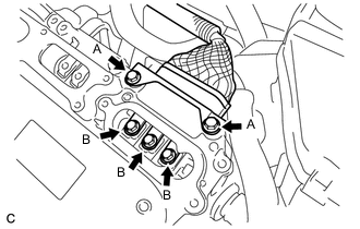
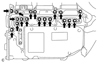
Temporarily install the No. 2 engine wire (high voltage cables of the air conditioning) with the 5 bolts to the inverter with converter assembly.
Note
To prevent the threads from being damaged, make sure to perform this step by hand.
-
Fully tighten the 2 bolts A.
- Torque:
- 9.2 N*m { 94 kgf*cm, 81 in.*lbf }
Note
Be sure to use a torque wrench to tighten the bolts.
-
Fully tighten the 2 bolts B.
- Torque:
- 8.0 N*m { 82 kgf*cm, 71 in.*lbf }
Note
Be sure to use a torque wrench to tighten the bolts.
-
Install the bracket with the bolt C.
- Torque:
- 9.4 N*m { 96 kgf*cm, 83 in.*lbf }
-
-
CONNECT MOTOR CABLE
CAUTION:
Wear insulated gloves.
Note
Do not allow any foreign matter or water to enter the inverter with converter assembly.
-
Connect the motor cable (MG2).
-
Temporarily install the high voltage cable of the motor cable (MG2) with the 5 bolts to the inverter with converter assembly.
Note
To prevent the threads from being damaged, make sure to perform this step by hand.
-
Fully tighten the 2 bolts A.
- Torque:
- 9.2 N*m { 94 kgf*cm, 81 in.*lbf }
Note
Be sure to use a torque wrench to tighten the bolts.
-
Fully tighten the 3 bolts B.
- Torque:
- 8.0 N*m { 82 kgf*cm, 71 in.*lbf }
Note
Be sure to use a torque wrench to tighten the bolts.
-
Connect the harness clamp.
-
-
Connect the motor cable (MG1).
-
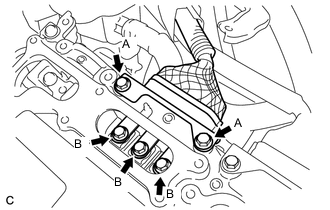
Temporarily install the high voltage cable of the motor cable (MG1) with the 5 bolts to the inverter with converter assembly.
Note
To prevent the threads from being damaged, make sure to perform this step by hand.
-
Fully tighten the 2 bolts A.
- Torque:
- 9.2 N*m { 94 kgf*cm, 81 in.*lbf }
Note
Be sure to use a torque wrench to tighten the bolts.
-
Fully tighten the 3 bolts B.
- Torque:
- 8.0 N*m { 82 kgf*cm, 71 in.*lbf }
Note
Be sure to use a torque wrench to tighten the bolts.
-
-
-
CONNECT FRAME WIRE
CAUTION:
Wear insulated gloves.
Note
Do not allow any foreign matter or water to enter the inverter with converter assembly.
-
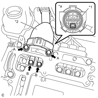
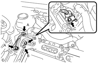
Text in Illustration *1 Interlock Connector *2 Frame Wire (High voltage cables of hybrid battery) *a Front view of frame wire connector Temporarily install the frame wire (high voltage cables of the hybrid battery) with the 4 bolts to the inverter with converter assembly.
Note
-
Make sure that the interlock connector is fully engaged.
-
To prevent the threads from being damaged, make sure to perform this step by hand.
-
-
Fully tighten the 2 bolts A.
- Torque:
- 9.2 N*m { 94 kgf*cm, 81 in.*lbf }
Note
Be sure to use a torque wrench to tighten the bolts.
-
Fully tighten the 2 bolts B.
- Torque:
- 8.0 N*m { 82 kgf*cm, 71 in.*lbf }
Note
Be sure to use a torque wrench to tighten the bolts.
-
Connect the harness clamp.
-
-
CHECK HIGH VOLTAGE CABLE CONNECTION
CAUTION:
Wear insulated gloves.
Note
Do not allow any foreign matter or water to enter the inverter with converter assembly.
-
Check that each connector and terminal is firmly installed.
Note
Make sure that the bolts are fully tightened.
-
-
INSTALL INVERTER COVER
CAUTION:
Wear insulated gloves.
-
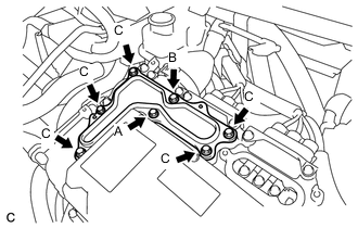
Temporarily install the inverter cover with the 7 bolts to the inverter with converter assembly.
CAUTION:
An interlock connector is installed to the inverter terminal cover. Make sure to install the inverter terminal cover after installing the inverter cover.
Note
Visually confirm that the inverter cover waterproofing rubber is securely installed before installing the inverter cover.
-
Fully tighten the bolt A.
- Torque:
- 11 N*m { 112 kgf*cm, 8 ft.*lbf }
-
Fully tighten the bolt B.
- Torque:
- 11 N*m { 112 kgf*cm, 8 ft.*lbf }
-
Fully tighten the 5 bolts C.
- Torque:
- 11 N*m { 112 kgf*cm, 8 ft.*lbf }
-
-
INSTALL INVERTER TERMINAL COVER
CAUTION:
Wear insulated gloves.
-
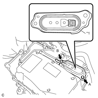
Text in Illustration *1 Interlock Connector Temporarily install the inverter terminal cover with the 2 bolts to the inverter with converter assembly.
CAUTION:
An interlock connector is installed to the inverter terminal cover. Make sure to install the inverter terminal cover after installing the inverter cover.
Note
-
Visually confirm that the inverter terminal cover waterproofing rubber is securely installed before installing the inverter terminal cover.
-
Make sure that the interlock connector is fully engaged.
-
-
Fully tighten the bolt A.
- Torque:
- 11 N*m { 112 kgf*cm, 8 ft.*lbf }
-
Fully tighten the bolt B.
- Torque:
- 11 N*m { 112 kgf*cm, 8 ft.*lbf }
-
-
INSTALL ENGINE ROOM MAIN WIRE
CAUTION:
Wear insulated gloves.
Note
Do not allow any foreign matter or water to enter the inverter with converter assembly.
-
Connect the clamp.
-
Connect the engine room main wire with the 2 bolts.
- Torque:
- 9.4 N*m { 96 kgf*cm, 83 in.*lbf }
-
Connect the hose clamp.
-
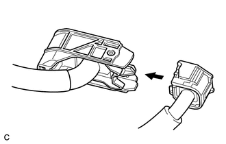
Connect the engine wire to the engine room main wire.
Note
Make sure that the interlock is fully engaged.
-
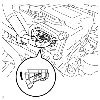
Connect the connector to the inverter with converter assembly and lock the connector with the lock lever.
-
-
INSTALL HOOD STAY HOLDER
-
Engage the claw and install the hood stay holder.
-
-
INSTALL SERVICE PLUG GRIP
-
CONNECT CABLE TO NEGATIVE AUXILIARY BATTERY TERMINAL
-
INSTALL CENTER FRONT FLOOR COVER (for Front Floor Cover Type A)
-
INSTALL FRONT FLOOR COVER LH (for Front Floor Cover Type A)
-
INSTALL FRONT FLOOR COVER RH (for Front Floor Cover Type A)
-
INSTALL FRONT FLOOR COVER RH (for Front Floor Cover Type B)
-
INSTALL CENTER FRONT FLOOR COVER (for Front Floor Cover Type B)
-
ADD COOLANT (for Inverter)
-
INSPECT FOR COOLANT LEAK (for Inverter)