BATTERY SMART UNIT INSTALLATION
PROCEDURE
-
INSTALL BATTERY SMART UNIT (BATTERY VOLTAGE SENSOR)
CAUTION:
Wear insulated gloves.
-
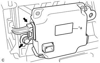
Text in Illustration *a Red Label Install the battery smart unit with the bolt.
- Torque:
- 7.5 N*m { 76 kgf*cm, 66 in.*lbf }
Note
Check color of the label.
-
Connect the connector.
Note
The connector should be connected securely.
-
-
INSTALL NO. 2 HYBRID VEHICLE BATTERY CARRIER BRACKET SUB-ASSEMBLY
CAUTION:
Wear insulated gloves.
-
Install the No. 2 hybrid vehicle battery carrier bracket sub-assembly with the bolt and 2 nuts.
- Torque:
- 7.5 N*m { 76 kgf*cm, 66 in.*lbf }
-
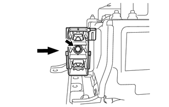
Engage the 3 clamps.
-
Connect the connector.
Note
The connector should be connected securely.
-
-
INSTALL NO. 1 HYBRID BATTERY SHIELD SUB-ASSEMBLY
CAUTION:
Wear insulated gloves.
-
Install the No. 1 hybrid battery shield sub-assembly with the 2 bolts and 2 nuts.
- Torque:
- 7.5 N*m { 76 kgf*cm, 66 in.*lbf }
-
Install the electric vehicle battery plug with the bolt as shown in the illustration.
- Torque:
- 7.5 N*m { 76 kgf*cm, 66 in.*lbf }
-
-
INSTALL HYBRID BATTERY SERVICE PLUG COVER
CAUTION:
Wear insulated gloves.
-
Install the hybrid battery service plug cover with the 2 nuts.
- Torque:
- 7.5 N*m { 76 kgf*cm, 66 in.*lbf }
-
-
CONNECT WIRE HARNESS
-
Engage the clamp and connect the wire harness.
-
Connect the 2 connectors.
-
-
INSTALL NO. 1 HYBRID BATTERY EXHAUST DUCT
-
Install the No. 1 hybrid battery exhaust duct with the clip.
-
-
INSTALL REAR SEAT CUSHION LEG SUB-ASSEMBLY
-
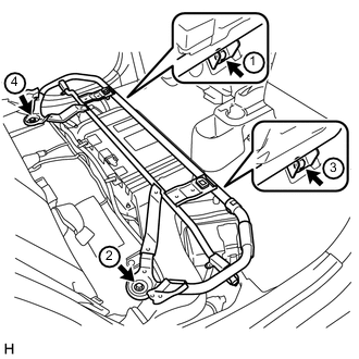
Temporarily install the rear seat cushion leg sub-assembly with the 4 bolts.
-
Tighten the 4 bolts in the order shown in the illustration.
- Torque:
- 42 N*m { 428 kgf*cm, 31 ft.*lbf }
-
-
INSTALL BENCH TYPE REAR SEAT CUSHION ASSEMBLY
-
INSTALL SERVICE PLUG GRIP
-
CONNECT CABLE TO NEGATIVE AUXILIARY BATTERY TERMINAL
-
INSTALL CENTER FRONT FLOOR COVER (for Front Floor Cover Type A)
-
Engage the 2 guides to install the center front floor cover.
-
Install the 3 clips.
-
-
INSTALL FRONT FLOOR COVER LH (for Front Floor Cover Type A)
-
Engage the 3 guides to install the front floor cover LH.
-
Engage the 2 clips.
-
Install the 2 clips.
-
-
INSTALL FRONT FLOOR COVER RH (for Front Floor Cover Type A)
-
Engage the 3 guides to install the front floor cover RH.
-
Engage the 2 clips.
-
Install the 2 clips.
-
-
INSTALL FRONT FLOOR COVER LH (for Front Floor Cover Type B)
-
Engage the 3 guides to install the front floor cover LH.
-
Install the clip.
-
-
INSTALL FRONT FLOOR COVER RH (for Front Floor Cover Type B)
-
Engage the 3 guides to install the front floor cover RH.
-
Install the clip.
-
-
INSTALL CENTER FRONT FLOOR COVER (for Front Floor Cover Type B)
-
Engage the 4 guides to install the center front floor cover.
-
Engage the 2 clips.
-
Install the 5 clips.
-