HYBRID CONTROL SYSTEM ECU Power Source Circuit
DESCRIPTION
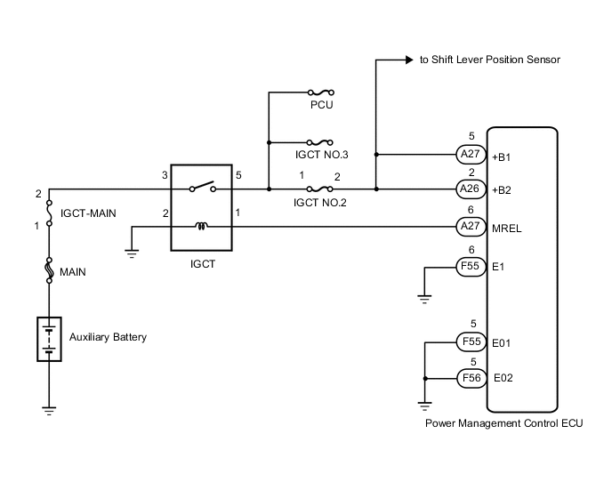
If the ignition switch is on (IG), the power management control ECU applies current to the MREL terminal to turn the IGCT relay on. This supplies power to the +B1 and +B2 terminals.
WIRING DIAGRAM
PROCEDURE
-
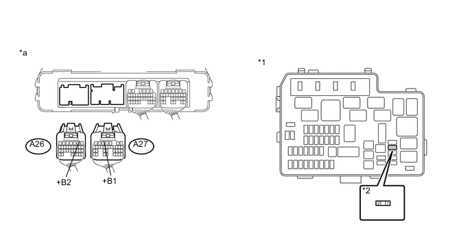
CHECK POWER MANAGEMENT CONTROL ECU (+B1, +B2 VOLTAGE)
-
Turn the ignition switch to ON (IG).
-
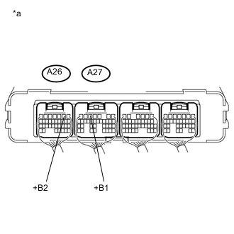
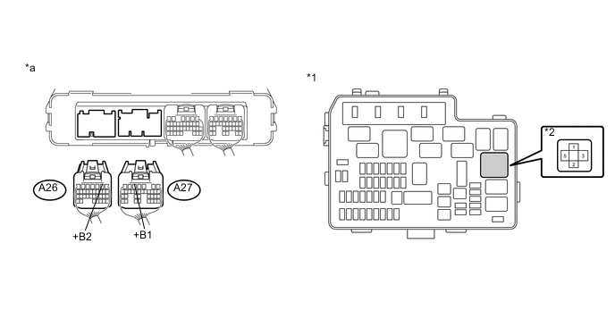
Text in Illustration *a Component with harness connected
(Power Management Control ECU)
Measure the voltage according to the value(s) in the table below.
Standard Voltage Tester Connection Switch Condition Specified Condition A27-5 (+B1) - Body ground Ignition switch ON (IG) 11 to 14 V A26-2 (+B2) - Body ground Ignition switch ON (IG) 11 to 14 V -
Turn the ignition switch off.
NG 
CHECK POWER MANAGEMENT CONTROL ECU (MREL VOLTAGE) Click here
OK 
-
-
CHECK HARNESS AND CONNECTOR (POWER MANAGEMENT CONTROL ECU - BODY GROUND)
-
Disconnect the power management control ECU connectors.
-
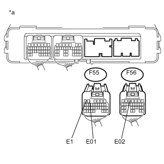
Text in Illustration *a Rear view of wire harness connector
(to Power Management Control ECU)
Measure the resistance according to the value(s) in the table below.
Standard Resistance Tester Connection Condition Specified Condition F55-5 (E01) - Body ground Always Below 1 Ω F55-6 (E1) - Body ground Always Below 1 Ω F56-5 (E02) - Body ground Always Below 1 Ω -
Connect the power management control ECU connectors.
OK 
GO TO PROBLEM SYMPTOMS TABLE Click here
NG
REPAIR OR REPLACE HARNESS OR CONNECTOR
-
-
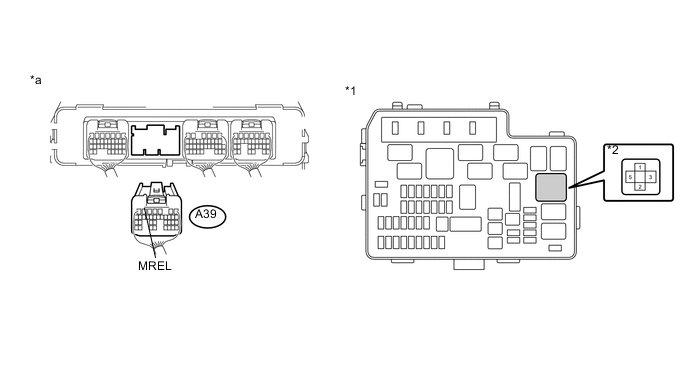
CHECK POWER MANAGEMENT CONTROL ECU (MREL VOLTAGE)
-
Turn the ignition switch to ON (IG).
-
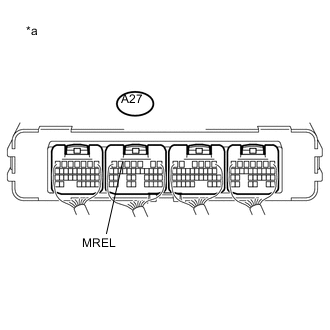
Text in Illustration *a Component with harness connected
(Power Management Control ECU)
Measure the voltage according to the value(s) in the table below.
Standard Voltage Tester Connection Switch Condition Specified Condition A27-6 (MREL) - Body ground Ignition switch ON (IG) 11 to 14 V
NG
REPLACE POWER MANAGEMENT CONTROL ECU Click here
OK
-
-
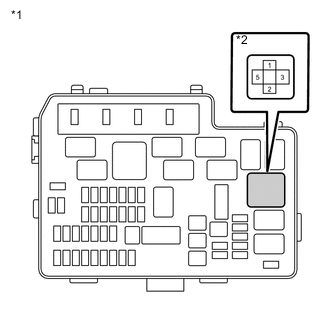
CHECK FUSE (IGCT NO. 2)
-
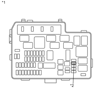
Text in Illustration *1 No. 2 Engine Room Relay Block *2 IGCT NO. 2 Fuse Remove the IGCT NO. 2 fuse from the No. 2 engine room relay block.
-
Measure the resistance according to the value(s) in the table below.
Standard Resistance Tester Connection Condition Specified Condition IGCT NO. 2 fuse terminals Always Below 1 Ω -
Install the IGCT NO. 2 fuse.
NG
CHECK HARNESS AND CONNECTOR (POWER MANAGEMENT CONTROL ECU - NO. 2 ENGINE ROOM RELAY BLOCK) Click here
OK
-
-
CHECK FUSE (IGCT-MAIN)
-
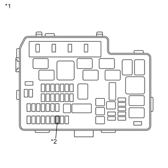
Text in Illustration *1 No. 2 Engine Room Relay Block *2 IGCT-MAIN Fuse Remove the IGCT-MAIN fuse from the No. 2 engine room relay block.
-
Measure the resistance according to the value(s) in the table below.
Standard Resistance Tester Connection Condition Specified Condition IGCT-MAIN fuse terminals Always Below 1 Ω -
Install the IGCT-MAIN fuse.
NG
CHECK HARNESS AND CONNECTOR (NO. 2 ENGINE ROOM RELAY BLOCK) Click here
OK
-
-
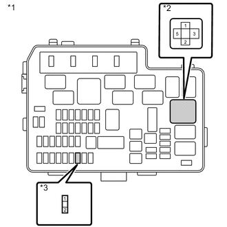
INSPECT RELAY (IGCT)
-
Remove the IGCT relay from the No. 2 engine room relay block.
-
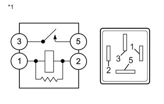
Text in Illustration *1 IGCT Relay Measure the resistance according to the value(s) in the table below.
Standard Resistance Tester Connection Condition Specified Condition 3 - 5 Auxiliary battery voltage is not applied between terminals 1 and 2 10 kΩ or higher Auxiliary battery voltage is applied between terminals 1 and 2 Below 1 Ω -
Install the IGCT relay.
NG
REPLACE RELAY (IGCT)
OK
-
-
CHECK HARNESS AND CONNECTOR (POWER MANAGEMENT CONTROL ECU - NO. 2 ENGINE ROOM RELAY BLOCK)
-
Remove the IGCT relay from the No. 2 engine room relay block.
-
Disconnect the power management control ECU connectors.
-
Measure the resistance according to the value(s) in the table below.
Text in Illustration *1 No. 2 Engine Room Relay Block *2 IGCT Relay *a Rear view of wire harness connector
(to Power Management Control ECU)
- - Standard Resistance Tester Connection Condition Specified Condition A27-5 (+B1) - 5 (IGCT relay) Always Below 1 Ω A26-2 (+B2) - 5 (IGCT relay) Always Below 1 Ω -
Install the IGCT relay.
-
Connect the power management control ECU connectors.
NG
REPLACE FUSE (IGCT MAIN)
OK
-
-
CHECK HARNESS AND CONNECTOR (NO. 2 ENGINE ROOM RELAY BLOCK)
-
Remove the IGCT MAIN fuse from the No. 2 engine room relay block.
-
Remove the IGCT relay from the No. 2 engine room relay block.
-
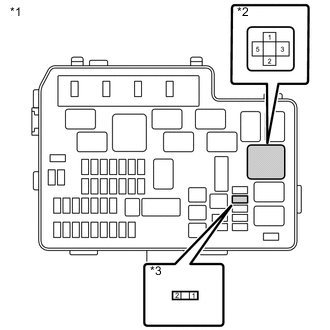
Text in Illustration *1 No. 2 Engine Room Relay Block *2 IGCT Relay *3 IGCT MAIN Fuse Measure the resistance according to the value(s) in the table below.
Standard Resistance Tester Connection Condition Specified Condition 3 (IGCT relay) - 2 (IGCT MAIN fuse) Always Below 1 Ω -
Install the IGCT MAIN fuse.
-
Install the IGCT relay.
NG
REPAIR OR REPLACE HARNESS OR CONNECTOR
OK
-
-
CHECK HARNESS AND CONNECTOR (POWER MANAGEMENT CONTROL ECU - NO. 2 ENGINE ROOM RELAY BLOCK)
-
Remove the IGCT relay from the No. 2 engine room relay block.
-
Disconnect the power management control ECU connector.
-
Measure the resistance according to the value(s) in the table below.
Text in Illustration *1 No. 2 Engine Room Relay Block *2 IGCT Relay *a Rear view of wire harness connector
(to Power Management Control ECU)
- - Standard Resistance Tester Connection Condition Specified Condition A27-6 (MREL) - 1 (IGCT relay) Always Below 1 Ω A27-6 (MREL) or 1 (IGCT relay) - Body ground and other terminals Always 10 kΩ or higher -
Install the IGCT relay.
-
Connect the power management control ECU connectors.
NG
REPAIR OR REPLACE HARNESS OR CONNECTOR
OK
-
-
CHECK HARNESS AND CONNECTOR (NO. 2 ENGINE ROOM RELAY BLOCK - BODY GROUND)
-
Remove the IGCT relay from the No. 2 engine room relay block.
-
Text in Illustration *1 No. 2 Engine Room Relay Block *2 IGCT Relay Measure the resistance according to the value(s) in the table below.
Standard Resistance Tester Connection Condition Specified Condition 2 (IGCT relay) - Body ground Always Below 1 Ω -
Install the IGCT relay.
OK
CHECK FOR INTERMITTENT PROBLEMS Click here
NG
REPAIR OR REPLACE HARNESS OR CONNECTOR
-
-
CHECK HARNESS AND CONNECTOR (POWER MANAGEMENT CONTROL ECU - NO. 2 ENGINE ROOM RELAY BLOCK)
-
Disconnect connector C23 from the shift lever position sensor.
-
Remove the IGCT NO. 2 fuse from the No. 2 engine room relay block.
-
Disconnect the power management control ECU connectors.
-
Measure the resistance according to the value(s) in the table below.
Text in Illustration *1 No. 2 Engine Room Relay Block *2 IGCT NO. 2 Fuse *a Rear view of wire harness connector
(to Power Management Control ECU)
- - Standard Resistance Tester Connection Condition Specified Condition A27-5 (+B1) or 2 (IGCT NO. 2 fuse) - Body ground and other terminals Always 10 kΩ or higher A26-2 (+B2) or 2 (IGCT NO. 2 fuse) - Body ground and other terminals Always 10 kΩ or higher -
Install the IGCT NO. 2 fuse.
-
Connect the shift lever position sensor connector.
-
Connect the power management control ECU connectors.
OK
REPLACE FUSE (IGCT NO. 2)
NG
REPAIR OR REPLACE HARNESS OR CONNECTOR Click here
-
-
CHECK HARNESS AND CONNECTOR (NO. 2 ENGINE ROOM RELAY BLOCK)
-
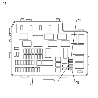
Text in Illustration *1 No. 2 Engine Room Relay Block *2 IGCT MAIN Fuse *3 IGCT NO. 2 Fuse *4 PCU Fuse *5 IGCT NO. 3 Fuse Remove the IGCT MAIN fuse, IGCT NO. 2 fuse, IGCT NO. 3 fuse and PCU fuse from the No. 2 engine room relay block.
-
Remove the IGCT relay from the No. 2 engine room relay block.
-
Text in Illustration *1 No. 2 Engine Room Relay Block *2 IGCT Relay *3 IGCT MAIN Fuse Measure the resistance according to the value(s) in the table below.
Standard Resistance Tester Connection Condition Specified Condition 3 (IGCT relay) or 2 (IGCT MAIN fuse) - Body ground and other terminals Always 10 kΩ or higher -
Text in Illustration *1 No. 2 Engine Room Relay Block *2 IGCT Relay *3 IGCT NO. 2 Fuse Measure the resistance according to the value(s) in the table below.
Standard Resistance Tester Connection Condition Specified Condition 5 (IGCT relay) or 2 (IGCT NO. 2 fuse) - Body ground and other terminals Always 10 kΩ or higher -
Install the IGCT MAIN fuse, IGCT NO. 2 fuse, IGCT NO. 3 fuse and PCU fuse.
-
Install the IGCT relay.
OK
CHECK FOR INTERMITTENT PROBLEMS Click here
NG
REPAIR OR REPLACE HARNESS OR CONNECTOR Click here
-
-
REPAIR OR REPLACE HARNESS OR CONNECTOR
NEXT
REPLACE FUSE (IGCT NO. 2)
-
REPAIR OR REPLACE HARNESS OR CONNECTOR
NEXT
REPLACE FUSE (IGCT MAIN)