HYBRID BATTERY SYSTEM TERMINALS OF ECU
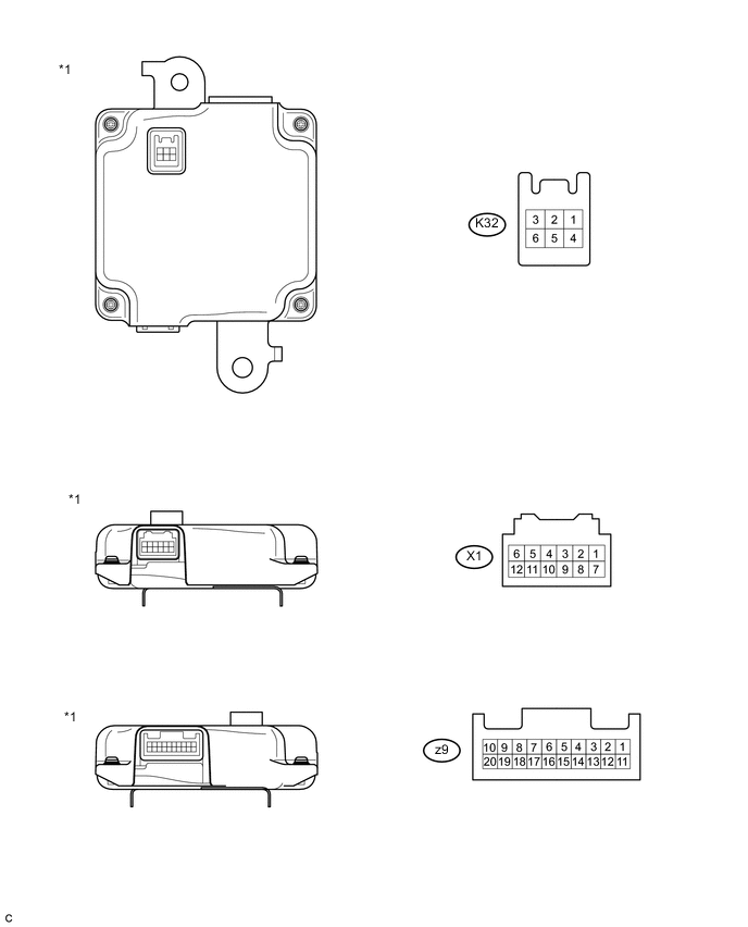
| *1 | Battery Smart Unit | - | - |
| Terminal No. (Symbols) |
Wiring Color | Terminal Description | Condition | Standard (V) |
|---|---|---|---|---|
| X1-1 (TCO) - X1-7 (GCO) | G - G | HV battery intake air temperature sensor | HV battery intake air temperature: -40 to 90°C (-40 to 194°F) | 4.8 (-40°C (-40°F)) to 1.0 (90°C (194°F)) |
| X1-2 (TB2) - X1-8 (GB2) | L - L | HV battery temperature sensor 2 | HV battery temperature: -40 to 90°C (-40 to 194°F) | 4.8 (-40°C (-40°F)) to 1.0 (90°C (194°F)) |
| X1-3 (TB1) - X1-9 (GB1) | W - W | HV battery temperature sensor 1 | HV battery temperature: -40 to 90°C (-40 to 194°F) | 4.8 (-40°C (-40°F)) to 1.0 (90°C (194°F)) |
| X1-4 (TBO) - X1-10 (GBO) | R - R | HV battery temperature sensor 0 | HV battery temperature: -40 to 90°C (-40 to 194°F) | 4.8 (-40°C (-40°F)) to 1.0 (90°C (194°F)) |
| X1-5 (IB) - X1-12 (GIB) | Y - B | Battery current sensor | Ignition switch ON (READY) | 0.5 to 4.5 |
| X1-6 (VIB) - X1-12 (GIB) | BR - B | Power source for battery current sensor | Ignition switch ON (IG) | 4.6 to 5.4 |
| K32-3 (IGCT) - K32-6 (GND) | L - W-B | Control signal | Ignition switch ON (READY) | 11 to 14 |
| K32-1 (BTH+) - K32-6 (GND) | R - W-B | Serial communication | Ignition switch ON (IG) | Pulse generation (waveform 1) |
| K32-4 (BTH-) - K32-6 (GND) | G - W-B | Serial communication | Ignition switch ON (IG) | Pulse generation (waveform 2) |
| K32-5 (FP0) - K32-6 (GND) | B - W-B | Battery cooling blower No. 0 monitor signal | Cooling blower activated | Pulse generation |
| K32-6 (GND) - Body ground | W-B | Ground | Always (continuity check) | Below 1 Ω |
-
Oscilloscope waveforms
Tech Tips
Oscilloscope waveform samples are provided here for informational purposes. Noise and fluttering waveforms have been omitted.
-
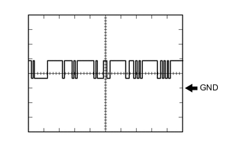
Waveform 1
Item Content Terminal K32-1 (BTH+) - K32-6 (GND) Equipment Setting 2 V/DIV., 500 μs/DIV. Condition Ignition switch ON (IG) Tech Tips
The waveform will vary depending on the content of the digital communication (digital signal).
-
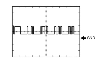
Waveform 2
Item Content Terminal K32-4 (BTH-) - K32-6 (GND) Equipment Setting 2 V/DIV., 500 μs/DIV. Condition Ignition switch ON (IG) Tech Tips
The waveform will vary depending on the content of the digital communication (digital signal).
-
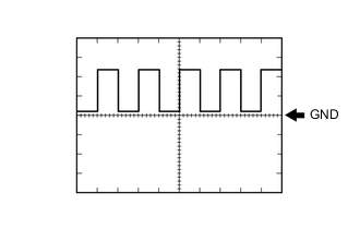
Waveform 3
Item Content Terminal K32-5 (FP0) - K32-6 (GND) Equipment Setting 5 V/DIV., 1ms/DIV. Condition Battery cooling blower assembly operating (Active Test of cooling fan being performed) Tech Tips
The frequency of the waveform will vary with the operating speed of the battery cooling blower assembly.
-