HYBRID CONTROL SYSTEM, Diagnostic DTC:P2532-772
| DTC Code | DTC Name |
|---|---|
| P2532-772 | Ignition Switch Run Position Circuit High |
DESCRIPTION
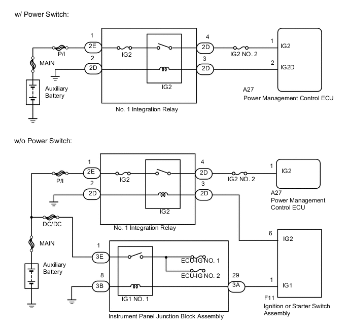
w/ Power Switch:
The power source and HV CPU processors and their functions are integrated into the power management control ECU. The power source CPU and HV CPU use CAN communication to communicate with each other inside the power management control ECU. The power source CPU controls the opening and closing of the IG2 relay. The HV CPU detects that the IG2 relay is stuck ON (closed) based on relay operation information received from the power source CPU via CAN communication.
| DTC No. | INF Code | DTC Detection Condition | Trouble Area |
|---|---|---|---|
| P2532 | 772 | Voltage is still applied to IG2 terminal although an IG2 relay off command is received from the power source CPU. |
|
w/o Power Switch:
The power management control ECU detects that the IG2 relay is stuck ON (closed) based on IG signals received from the main body ECU via CAN communication.
| DTC No. | INF Code | DTC Detection Condition | Trouble Area |
|---|---|---|---|
| P2532 | 772 | When communication from ECUs with an IG1 power source is interrupted and power source voltage is still applied to terminal IG2. |
|
Tech Tips
If DTC P2532-772 is stored, the vehicle will turn off.
WIRING DIAGRAM
CAUTION / NOTICE / HINT
Tech Tips
After the repair, clear the DTCs and perform the following procedure to check that DTCs are not output.
-
Turn the ignition switch to ON (IG) and wait for 15 seconds or more.
-
Turn the ignition switch off and wait for 30 seconds or more.
PROCEDURE
-
CHECK VEHICLE CONDITION
-
Check the vehicle condition.
Result Result Proceed to w/ Power Switch A w/o Power Switch B
B 
CLEAR DTC Click here
A 
-
-
CHECK HARNESS AND CONNECTOR (+B SHORT)
-
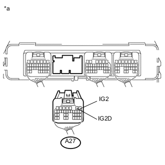
Text in Illustration *a Rear view of wire harness connector
(to Power Management Control ECU)
Disconnect the power management control ECU connector.
-
Measure the voltage according to the value(s) in the table below.
Standard Voltage Tester Connection Switch Condition Specified Condition A27-1 (IG2) - Body ground Ignition switch off Below 1 V A27-2 (IG2D) - Body ground Ignition switch off Below 1 V Result Result Proceed to NG A OK B -
Connect the power management control ECU connector.
B 
REPLACE POWER MANAGEMENT CONTROL ECU Click here
A
-
-
CHECK HARNESS AND CONNECTOR (POWER MANAGEMENT CONTROL ECU - IG2 RELAY)
-
Disconnect the power management control ECU connector.
-
Remove the No. 1 integration relay from the No. 2 engine room relay block.
-

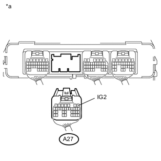
Text in Illustration *a Rear view of wire harness connector
(to Power Management Control ECU)
Measure the voltage according to the value(s) in the table below.
Standard Voltage Tester Connection Switch Condition Specified Condition A27-1 (IG2) - Body ground Ignition switch off Below 1 V A27-2 (IG2D) - Body ground Ignition switch off Below 1 V -
Install the No. 1 integration relay.
-
Connect the power management control ECU connector.
OK
REPLACE NO. 1 INTEGRATION RELAY Click here
NG
REPAIR OR REPLACE HARNESS OR CONNECTOR
-
-
CLEAR DTC
-
Connect the GTS to the DLC3.
-
Turn the ignition switch to ON (IG).
-
Enter the following menus: Powertrain / Hybrid Control / Trouble Codes.
-
Read and record the DTCs and freeze frame data.
-
Clear the DTCs and freeze frame data.
-
Turn the ignition switch off.
NEXT
-
-
CHECK DTC OUTPUT (HYBRID CONTROL)
-
Connect the GTS to the DLC3.
-
Turn the ignition switch to ON (IG).
-
Enter the following menus: Powertrain / Hybrid Control / Trouble Codes.
-
Check if DTCs are output.
Result Result Proceed to Only P2532-772 is output or P2532-772 and DTCs other than U0140-146 are also output. A U0140-146 is output. B DTCs other than P2532-772 or U0140-146 are output. C No DTCs are output. D -
Turn the ignition switch off.
B
GO TO DTC CHART (U0140-146) Click here
C
GO TO DTC CHART (HYBRID CONTROL SYSTEM) Click here
D
CHECK DTC OUTPUT (HYBRID CONTROL) Click here
A
-
-
CHECK FUSE (ECU-IG NO. 1, ECU-IG NO. 2)
-
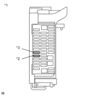
Text in Illustration *1 Instrument panel junction block assembly *2 ECU-IG NO. 1 fuse *3 ECU-IG NO. 2 fuse Remove the ECU-IG NO. 1 fuse and ECU-IG NO. 2 fuse from the instrument panel junction block assembly.
-
Measure the resistance according to the value(s) in the table below.
Standard Resistance Tester Connection Condition Specified Condition ECU-IG NO. 1 fuse terminal Always Below 1 Ω ECU-IG NO. 2 fuse terminal Always Below 1 Ω -
Install the ECU-IG NO. 1 fuse and ECU-IG NO. 2 fuse.
NG
REPLACE FUSE (ECU-IG NO. 1, ECU-IG NO. 2)
OK
-
-
CHECK HARNESS AND CONNECTOR (IG1 NO. 1 RELAY POWER SOURCE CIRCUIT)
-
Disconnect the instrument panel junction block assembly connector.
-
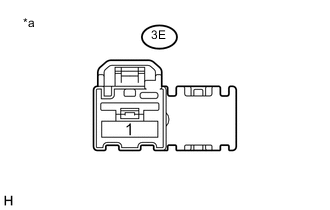
Text in Illustration *a Front view of wire harness connector
(to Instrument Panel Junction Block Assembly)
Measure the voltage according to the value(s) in the table below.
Standard Voltage Tester Connection Switch Condition Specified Condition 3E-1 - Body ground Ignition switch off 11 to 14 V -
Connect the instrument panel junction block assembly connector.
NG
REPAIR OR REPLACE HARNESS OR CONNECTOR
OK
-
-
CHECK HARNESS AND CONNECTOR (IG1 NO. 1 RELAY BODY GROUND)
-
Disconnect the instrument panel junction block assembly connector.
-
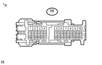
Text in Illustration *a Front view of wire harness connector
(to Instrument Panel Junction Block Assembly)
Measure the resistance according to the value(s) in the table below.
Standard Resistance Tester Connection Switch Condition Specified Condition 3B-8 - Body ground Ignition switch off Below 1 Ω -
Connect the instrument panel junction block assembly connector.
OK
REPLACE INSTRUMENT PANEL JUNCTION BLOCK ASSEMBLY Click here
NG
REPAIR OR REPLACE HARNESS OR CONNECTOR
-
-
CHECK DTC OUTPUT (HYBRID CONTROL)
-
Turn the ignition switch off and leave the vehicle as it is for 10 seconds or more.
-
Connect the GTS to the DLC3.
-
Turn the ignition switch to ON (IG).
-
Enter the following menus: Powertrain / Hybrid Control / Trouble Codes.
-
Check if DTCs are output.
Result Result Proceed to DTC P2532-772 is output. A No DTC is output. B -
Turn the ignition switch off.
B
CHECK FOR INTERMITTENT PROBLEMS Click here
A
-
-
CHECK HARNESS AND CONNECTOR (+B SHORT)
-
Disconnect the power management control ECU connector.
-
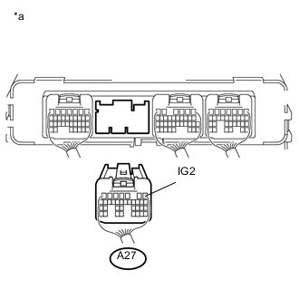
Text in Illustration *a Rear view of wire harness connector
(to Power Management Control ECU)
Measure the voltage according to the value(s) in the table below.
Standard Voltage Tester Connection Switch Condition Specified Condition A27-1 (IG2) - Body ground Ignition switch off Below 1 V Result Result Proceed to NG A OK B -
Connect the power management control ECU connector.
B
REPLACE POWER MANAGEMENT CONTROL ECU Click here
A
-
-
CHECK HARNESS AND CONNECTOR (POWER MANAGEMENT CONTROL ECU - IG2 RELAY)
-
Disconnect the power management control ECU connector.
-
Remove the No. 1 integration relay from the No. 2 engine room relay block.
-
Text in Illustration *a Rear view of wire harness connector
(to Power Management Control ECU)
Measure the voltage according to the value(s) in the table below.
Standard Voltage Tester Connection Switch Condition Specified Condition A27-1 (IG2) - Body ground Ignition switch off Below 1 V -
Install the No. 1 integration relay.
-
Connect the power management control ECU connector.
NG
REPAIR OR REPLACE HARNESS OR CONNECTOR
OK
-
-
INSPECT NO. 1 INTEGRATION RELAY (IG2 RELAY)
NG
REPLACE NO. 1 INTEGRATION RELAY Click here
OK
-
CHECK HARNESS AND CONNECTOR (IGNITION OR STARTER SWITCH ASSEMBLY - IG2 RELAY)
-
Disconnect the ignition or starter switch assembly connector.
-
Remove the No. 1 integration relay from the No. 2 engine room relay block.
-
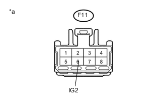
Text in Illustration *a Front view of wire harness connector
(to Ignition or Starter Switch Assembly)
Measure the voltage according to the value(s) in the table below.
Standard Voltage Tester Connection Switch Condition Specified Condition F11-6 (IG2) - Body ground Ignition switch off Below 1 V -
Install the No. 1 integration relay.
-
Connect the ignition or starter switch assembly connector.
OK
REPLACE IGNITION OR STARTER SWITCH ASSEMBLY Click here
NG
REPAIR OR REPLACE HARNESS OR CONNECTOR
-