HYBRID CONTROL SYSTEM, Diagnostic DTC:P321E-318
| DTC Code | DTC Name |
|---|---|
| P321E-318 | All HV Gate Blocking Range/Performance |
DESCRIPTION
The hybrid vehicle control ECU sends a block signal to the motor generator control ECU (MG ECU) to shutdown the power supply to the motor. When the system is not in the on (READY) state, it sends an HSDN (MG shutdown signal) signal from the hybrid vehicle control ECU to the motor generator control ECU (MG ECU) to check the function of the HV gate block. When a malfunction is detected in the HV gate block function, DTCs are stored.
| DTC No. | INF Code | DTC Detection Condition | Trouble Area |
|---|---|---|---|
| P321E | 318 | An open or ground short in the HV gate block signal circuit when the gate is operating. When the HV gate block function check is performed (when the ignition switch is turned from on (READY) to off), the inverter voltage (VH) drops and current flows in the inverter. (Both generator (MG1) and motor (MG2) are malfunctioning.) (1 trip detection logic) |
|
| DTC No. | Data List |
|---|---|
| P321E-318 |
|
WIRING DIAGRAM
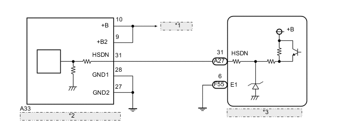
| *1 | to PCU Fuse |
| *2 | Inverter with Converter Assembly |
| *3 | Hybrid Vehicle Control ECU |
CAUTION / NOTICE / HINT
CAUTION:
-
Before inspecting the high-voltage system or disconnecting the low voltage connector of the inverter with converter assembly, take safety precautions such as wearing insulated gloves and removing the service plug grip to prevent electrical shocks. After removing the service plug grip, put it in your pocket to prevent other technicians from accidentally reconnecting it while you are working on the high-voltage system.
-
After removing the service plug grip, wait for at least 10 minutes before touching any of the high-voltage connectors or terminals. After waiting for 10 minutes, check the voltage at the terminals in the inspection point in the inverter with converter assembly. The voltage should be 0 V before beginning work Click here.
Tech Tips
Waiting for at least 10 minutes is required to discharge the high-voltage capacitor inside the inverter with converter assembly.
Note
After turning the ignition switch off, waiting time may be required before disconnecting the cable from the negative (-) auxiliary battery terminal. Therefore, make sure to read the disconnecting the cable from the negative (-) auxiliary battery terminal notices before proceeding with work Click here.
Tech Tips
After the repair, clear the DTCs and perform the following procedure to check that DTCs are not output.
-
Wait for 30 seconds or more with the vehicle stopped, the ignition switch to ON (READY) and the shift lever in P. Then turn the ignition switch off and wait for 60 seconds or more.
PROCEDURE
-
CHECK CONNECTOR CONNECTION CONDITION (HYBRID VEHICLE CONTROL ECU CONNECTOR)
-
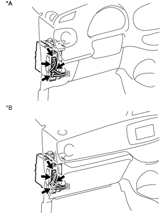
Text in Illustration *A for LHD *B for RHD Check the connector connections and contact pressure of the relevant terminals for the hybrid vehicle control ECU connectors Click here.
OK The connectors are connected securely and there are no contact pressure problems.
NG 
CONNECT SECURELY
OK 
-
-
CHECK CONNECTOR CONNECTION CONDITION (INVERTER WITH CONVERTER ASSEMBLY CONNECTOR)
CAUTION:
Be sure to wear insulated gloves.
-
Check that the service plug grip is not installed.
Note
After removing the service plug grip, do not turn the ignition switch to ON (READY), unless instructed by the repair manual because this may cause a malfunction.
-
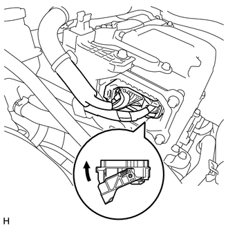
Check the connector connections and contact pressure of the low voltage connectors of the inverter with converter assembly Click here.
Note
Before disconnecting the connector, confirm that it is properly connected by checking that the locking claws are engaged and that the connector does not pull out.
OK The connectors are connected securely and there are no contact pressure problems. Tech Tips
When connecting the connector, insert it with the locking lever in the raised position. Rotate the lever downward and make sure that the connector is pulled into its socket. When the locking lever is in its fully closed position, a click will be heard as its locking claws engage. After the click is heard, pull up on the connector to confirm that it is properly connected.
NG
CONNECT SECURELY
OK
-
-
CHECK HARNESS AND CONNECTOR (INVERTER WITH CONVERTER ASSEMBLY - HYBRID VEHICLE CONTROL ECU)
CAUTION:
Be sure to wear insulated gloves.
-
Check that the service plug grip is not installed.
Note
After removing the service plug grip, do not turn the ignition switch to ON (READY), unless instructed by the repair manual because this may cause a malfunction.
-
Disconnect the inverter with converter assembly connector.
-
Disconnect the hybrid vehicle control ECU connector.
-
Measure the resistance according to the value(s) in the table below.
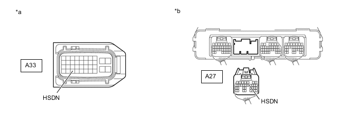
Standard Resistance Tester Connection Switch Condition Specified Condition A33-31 (HSDN) or A27-12 (HSDN) - Body ground and other terminals Ignition switch off 10 kΩ or higher A33-31 (HSDN) - A27-12 (HSDN) Ignition switch off Below 1 Ω Text in Illustration *a Front view of wire harness connector
(to Inverter with Converter Assembly)
*b Rear view of wire harness connector
(to Hybrid Vehicle Control ECU)
-
Connect the hybrid vehicle control ECU connector.
-
Connect the inverter with converter assembly connector.
NG
REPAIR OR REPLACE HARNESS OR CONNECTOR
OK
-
-
CHECK INVERTER WITH CONVERTER ASSEMBLY
CAUTION:
Be sure to wear insulated gloves.
-
Check that the service plug grip is not installed.
Note
After removing the service plug grip, do not turn the ignition switch to ON (READY), unless instructed by the repair manual because this may cause a malfunction.
-
Disconnect the inverter with converter assembly connector.
-
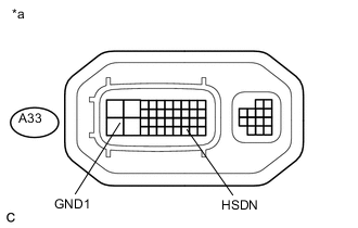
Text in Illustration *a Component without harness connected
(Inverter with Converter Assembly)
Measure the resistance according to the value(s) in the table below.
Standard Resistance Tester Connection Switch Condition Specified Condition A33-31 (HSDN) - A33-28 (GND1) Ignition switch off 2.65 to 3.55 kΩ -
Connect the inverter with converter assembly connector.
OK
REPLACE HYBRID VEHICLE CONTROL ECU Click here
NG
REFER TO REPLACE INVERTER WITH CONVERTER ASSEMBLY PARTS Click here
-