RELAY ON-VEHICLE INSPECTION
PROCEDURE
-
INSPECT HEADLIGHT DIMMER RELAY
-
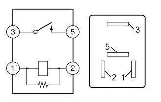
Measure the resistance according to the value(s) in the table below.
Standard Resistance Tester Connection Condition Specified Condition 3 - 5 Auxiliary battery voltage not applied to terminal 1 and 2 10 kΩ or higher Auxiliary battery voltage applied to terminal 1 and 2 Below 1 Ω If the result is not as specified, replace the headlight dimmer relay.
-
-
INSPECT HEADLIGHT RELAY
-
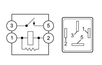
Measure the resistance according to the value(s) in the table below.
Standard Resistance Tester Connection Condition Specified Condition 3 - 5 Auxiliary battery voltage not applied to terminal 1 and 2 10 kΩ or higher Auxiliary battery voltage applied to terminal 1 and 2 Below 1 Ω If the result is not as specified, replace the headlight relay.
-
-
INSPECT FRONT FOG LIGHT RELAY
-
Measure the resistance according to the value(s) in the table below.
Standard Resistance Tester Connection Condition Specified Condition 3 - 5 Auxiliary battery voltage not applied to terminal 1 and 2 10 kΩ or higher Auxiliary battery voltage applied to terminal 1 and 2 Below 1 Ω If the result is not as specified, replace the front fog light relay.
-
-
INSPECT DAY TIME RUNNING LIGHT RELAY
-
Measure the resistance according to the value(s) in the table below.
Standard Resistance Tester Connection Condition Specified Condition 3 - 5 Auxiliary battery voltage not applied to terminal 1 and 2 10 kΩ or higher Auxiliary battery voltage applied to terminal 1 and 2 Below 1 Ω If the result is not as specified, replace the day time running light relay.
-
-
INSPECT BACK UP LIGHT RELAY
-
Measure the resistance according to the value(s) in the table below.
Standard Resistance Tester Connection Condition Specified Condition 3 - 5 Auxiliary battery voltage not applied to terminal 1 and 2 10 kΩ or higher Auxiliary battery voltage applied to terminal 1 and 2 Below 1 Ω If the result is not as specified, replace the back up light relay.
-
-
INSPECT STOP LIGHT RELAY (w/ Toyota Safety Sense)
-
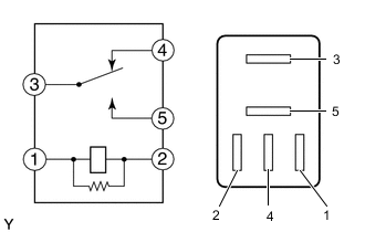
Measure the resistance according to the value(s) in the table below.
Standard Resistance Tester Connection Condition Specified Condition 3 - 4 Auxiliary battery voltage not applied Below 1 Ω Auxiliary battery voltage applied to terminal 1 and 2 10 kΩ or higher 3 - 5 Auxiliary battery voltage not applied 10 kΩ or higher Auxiliary battery voltage applied to terminal 1 and 2 Below 1 Ω If the result is not as specified, replace the stop light relay.
-