HAZARD WARNING SWITCH INSPECTION
PROCEDURE
-
INSPECT TELLTALE LIGHT ASSEMBLY
-
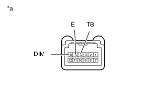
Text in Illustration *a Component without harness connected
(Telltale Light Assembly)
Check the hazard warning signal light switch function.
-
Measure the resistance according to the value(s) in the table below.
Standard Resistance: Tester Connection Switch Condition Specified Condition 4 (TB) - 5 (E) Pushed Below 1 Ω Not pushed 10 kΩ or higher If the result is not as specified, replace the telltale light assembly.
-
-
Check the illumination operation.
-
Apply auxiliary battery voltage to the telltale light assembly connector.
OK Condition Specified Condition Battery positive (+) → 6 (DIM)
Battery positive (-) → 5 (E)
The illumination comes on If the result is not as specified, replace the telltale light assembly.
-
-