HYBRID CONTROL SYSTEM, Diagnostic DTC:P0A09-591
| DTC Code | DTC Name |
|---|---|
| P0A09-591 | DC / DC Converter Status Circuit Low Input |
DESCRIPTION
The DC/DC converter varies output voltage based on voltage change signals (VLO signal line) received from the hybrid vehicle control ECU.
If the vehicle is being driven with an inoperative DC/DC converter, the voltage of the auxiliary battery will drop, which will prevent the continued operation of the vehicle. Therefore, the hybrid vehicle control ECU monitors the operation of the DC/DC converter and alerts the driver if it detects a malfunction.
| DTC No. | INF Code | DTC Detection Condition | Trouble Area |
|---|---|---|---|
| P0A09 | 591 | Open or short to ground in the signal line of DC/DC converter (VLO) (1 trip detection logic) |
|
WIRING DIAGRAM
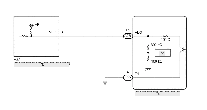
| *a | ADC |
| *b | Inverter with Converter Assembly |
| *c | Hybrid Vehicle Control ECU |
CAUTION / NOTICE / HINT
CAUTION:
-
Before inspecting the high-voltage system or disconnecting the low voltage connector of the inverter with converter assembly, take safety precautions such as wearing insulated gloves and removing the service plug grip to prevent electrical shocks. After removing the service plug grip, put it in your pocket to prevent other technicians from accidentally reconnecting it while you are working on the high-voltage system.
-
After removing the service plug grip, wait for at least 10 minutes before touching any of the high-voltage connectors or terminals. After waiting for 10 minutes, check the voltage at the terminals in the inspection point in the inverter with converter assembly. The voltage should be 0 V before beginning work Click here.
Tech Tips
Waiting for at least 10 minutes is required to discharge the high-voltage capacitor inside the inverter with converter assembly.
Note
After turning the ignition switch off, waiting time may be required before disconnecting the cable from the negative (-) auxiliary battery terminal. Therefore, make sure to read the disconnecting the cable from the negative (-) auxiliary battery terminal notices before proceeding with work Click here.
Tech Tips
After the repair, clear the DTCs and perform the following procedure to check that DTCs are not output.
-
Turn the ignition switch to ON (IG) and wait for 10 seconds or more.
PROCEDURE
-
CHECK CONNECTOR CONNECTION CONDITION (HYBRID VEHICLE CONTROL ECU CONNECTOR)
-
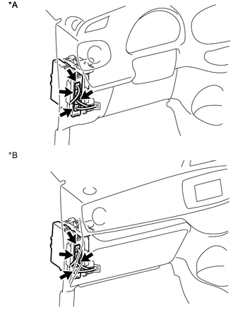
Text in Illustration *A for LHD *B for RHD Check the connector connections and contact pressure of the relevant terminals for the hybrid vehicle control ECU connectors Click here.
OK The connectors are connected securely and there are no contact pressure problems.
NG 
CONNECT SECURELY
OK 
-
-
CHECK CONNECTOR CONNECTION CONDITION (INVERTER WITH CONVERTER ASSEMBLY CONNECTOR)
CAUTION:
Be sure to wear insulated gloves.
-
Check that the service plug grip is not installed.
Note
After removing the service plug grip, do not turn the ignition switch to ON (READY), unless instructed by the repair manual because this may cause a malfunction.
-
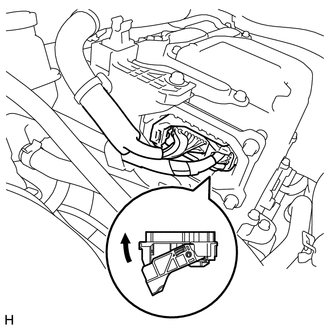
Check the connector connections and contact pressure of the low voltage connectors of the inverter with converter assembly Click here.
Note
Before disconnecting the connector, confirm that it is properly connected by checking that the locking claws are engaged and that the connector does not pull out.
OK The connectors are connected securely and there are no contact pressure problems. Tech Tips
When connecting the connector, insert it with the locking lever in the raised position. Rotate the lever downward and make sure that the connector is pulled into its socket. When the locking lever is in its fully closed position, a click will be heard as its locking claws engage. After the click is heard, pull up on the connector to confirm that it is properly connected.
NG
CONNECT SECURELY
OK
-
-
CHECK HYBRID VEHICLE CONTROL ECU (CHECK WAVEFORM)
-
Connect an oscilloscope between the hybrid vehicle control ECU terminals specified in the table below.
-
Turn the ignition switch to ON (IG).
-
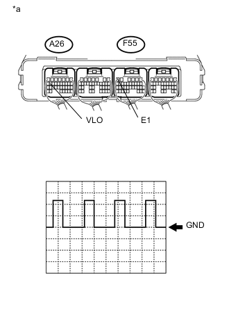
Text in Illustration *a Component with harness connected
(Hybrid Vehicle Control ECU)
Measure the waveform.
Item Content Terminal A26-16 (VLO) - F55-6 (E1) Equipment Setting 5 V/DIV., 50 ms/DIV. Condition Ignition switch ON (IG) OK The waveform appears as shown in the illustration. Tech Tips
-
Perform this inspection with the hybrid vehicle control ECU connector connected.
-
The waveform varies depending on the specified DC/DC converter voltage.
-
-
Turn the ignition switch off.
NG 
CHECK HARNESS AND CONNECTOR (RESISTANCE VALUE OF VLO INSIDE HYBRID VEHICLE CONTROL ECU) Click here
OK
-
-
CLEAR DTC
-
Connect the GTS to the DLC3.
-
Turn the ignition switch to ON (IG).
-
Enter the following menus: Powertrain / Hybrid Control / Trouble Codes.
-
Read and record the DTCs and freeze frame data.
-
Clear DTCs and freeze frame data.
-
Turn the ignition switch off.
NEXT
-
-
CHECK DTC OUTPUT (HYBRID CONTROL)
-
Connect the GTS to the DLC3.
-
Turn the ignition switch to ON (READY).
-
Enter the following menus: Powertrain / Hybrid Control / Trouble Codes.
-
Check if DTCs are output.
Result Result Proceed to P0A09-591 is not output. A P0A09-591 is output again. B -
Turn the ignition switch off.
A
CHECK FOR INTERMITTENT PROBLEMS Click here
B
REPLACE HYBRID VEHICLE CONTROL ECU Click here
-
-
CHECK HARNESS AND CONNECTOR (RESISTANCE VALUE OF VLO INSIDE HYBRID VEHICLE CONTROL ECU)
CAUTION:
Be sure to wear insulated gloves.
-
Check that the service plug grip is not installed.
Note
After removing the service plug grip, do not turn the ignition switch to ON (READY), unless instructed by the repair manual because this may cause a malfunction.
-
Disconnect the inverter with converter assembly connector.
-
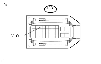
Text in Illustration *a Front view of wire harness connector
(to Inverter with Converter Assembly)
Measure the resistance according to the value(s) in the table below.
Standard Resistance Tester Connection Switch Condition Specified Condition A33-3 (VLO) - Body ground Ignition switch off 370 to 430 kΩ -
Connect the inverter with converter assembly connector.
OK
REFER TO REPLACE INVERTER WITH CONVERTER ASSEMBLY PARTS Click here
NG
-
-
CHECK HARNESS AND CONNECTOR (INVERTER WITH CONVERTER ASSEMBLY - HYBRID VEHICLE CONTROL ECU)
CAUTION:
Be sure to wear insulated gloves.
-
Check that the service plug grip is not installed.
Note
After removing the service plug grip, do not turn the ignition switch to ON (READY), unless instructed by the repair manual because this may cause a malfunction.
-
Disconnect the inverter with converter assembly connector.
-
Disconnect the hybrid vehicle control ECU connector.
-
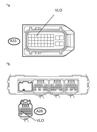
Text in Illustration *a Front view of wire harness connector
(to Inverter with Converter Assembly)
*b Rear view of wire harness connector
(to Hybrid Vehicle Control ECU)
Measure the resistance according to the value(s) in the table below.
Standard Resistance Tester Connection Switch Condition Specified Condition A33-3 (VLO) - A26-16 (VLO) Ignition switch off Below 1 Ω A33-3 (VLO) or A26-16 (VLO) - Body ground and other terminals Ignition switch off 10 kΩ or higher -
Connect the inverter with converter assembly connector.
-
Connect the hybrid vehicle control ECU connector.
OK
REPLACE HYBRID VEHICLE CONTROL ECU Click here
NG
REPAIR OR REPLACE HARNESS OR CONNECTOR
-