HYBRID CONTROL SYSTEM, Diagnostic DTC:P0617-142
| DTC Code | DTC Name |
|---|---|
| P0617-142 | Starter Relay Circuit High |
DESCRIPTION
w/ Power Switch:
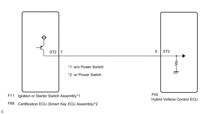
The hybrid vehicle control ECU monitors the ST signal received from the certification ECU (smart key ECU assembly). When an error is detected in the ST signal, this DTC is stored.
w/o Power Switch:
The hybrid vehicle control ECU monitors the ST signal received from the ignition or starter switch assembly. When an error is detected in the ST signal, this DTC is stored.
| DTC No. | INF Code | DTC Detection Condition | Trouble Area |
|---|---|---|---|
| P0617 | 142 | w/ Power Switch: An ST signal from the hybrid vehicle control ECU is on when the power switch is off. w/o Power Switch: Although the ignition switch is off, the hybrid vehicle control ECU receives a ST signal. (2 trip detection logic) |
|
WIRING DIAGRAM
CAUTION / NOTICE / HINT
Tech Tips
After the repair, clear the DTCs and perform the following procedure to check that DTCs are not output.
-
Turn the ignition switch off and wait for 30 seconds or more.
-
Turn the ignition switch to ON (READY) and wait for 15 seconds or more.
-
Turn the ignition switch off and wait for 30 seconds or more.
PROCEDURE
-
CHECK VEHICLE CONDITION
-
Check the vehicle condition.
Result Result Proceed to w/ Power Switch A w/o Power Switch B
B 
CHECK HARNESS AND CONNECTOR (ST2 TERMINAL VOLTAGE) Click here
A 
-
-
CHECK CONNECTOR CONNECTION CONDITION (HYBRID VEHICLE CONTROL ECU CONNECTOR)
-
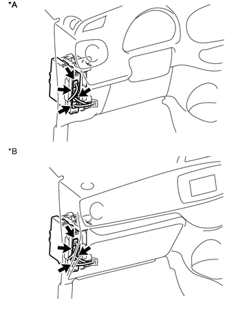
Text in Illustration *A for LHD *B for RHD Check the connector connections and contact pressure of the relevant terminals for the hybrid vehicle control ECU connectors Click here.
OK The connectors are connected securely and there are no contact pressure problems.
NG 
CONNECT SECURELY
OK
-
-
CHECK CONNECTOR CONNECTION CONDITION (CERTIFICATION ECU (SMART KEY ECU ASSEMBLY) CONNECTOR)
-
Check the connector connection condition of the certification ECU (smart key ECU assembly) Click here.
OK The connector is connected securely and there are no contact problems.
NG
CONNECT SECURELY
OK
-
-
CHECK HARNESS AND CONNECTOR (ST2 TERMINAL VOLTAGE)
-
Turn the power switch off.
-
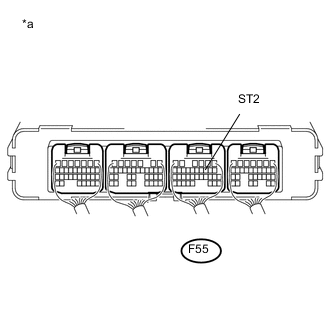
Text in Illustration *a Component with harness connected
(Hybrid Vehicle Control ECU)
Measure the voltage according to the value(s) in the table below.
Standard Voltage Tester Connection Switch Condition Specified Condition F55-9 (ST2) - Body ground Power switch off Below 1 V
OK
REPLACE HYBRID VEHICLE CONTROL ECU Click here
NG
-
-
CHECK HARNESS AND CONNECTOR (CERTIFICATION ECU (SMART KEY ECU ASSEMBLY) - HYBRID VEHICLE CONTROL ECU)
-
Disconnect connector F88 from the certification ECU (smart key ECU assembly) connector.
-

Text in Illustration *a Component with harness connected
(Hybrid Vehicle Control ECU)
Measure the voltage according to the value(s) in the table below.
Standard Voltage Tester Connection Switch Condition Specified Condition F55-9 (ST2) - Body ground Power switch off Below 1 V -
Connect the certification ECU (smart key ECU assembly) connector.
OK
REPLACE CERTIFICATION ECU (SMART KEY ECU ASSEMBLY)
NG
REPAIR OR REPLACE HARNESS OR CONNECTOR
-
-
CHECK HARNESS AND CONNECTOR (ST2 TERMINAL VOLTAGE)
-
Disconnect the hybrid vehicle control ECU connector.
-
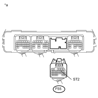
Text in Illustration *a Rear view of wire harness connector
(to Hybrid Vehicle Control ECU)
Measure the voltage according to the value(s) in the table below.
Standard Voltage Tester Connection Switch Condition Specified Condition F55-9 (ST2) - Body ground Ignition switch off Below 1 V -
Connect the hybrid vehicle control ECU connector.
NG
CHECK HARNESS AND CONNECTOR (IGNITION OR STARTER SWITCH ASSEMBLY - HYBRID VEHICLE CONTROL ECU) Click here
OK
-
-
CLEAR DTC
-
Connect the GTS to the DLC3.
-
Turn the ignition switch to ON (IG).
-
Enter the following menus: Powertrain / Hybrid Control / Trouble Codes.
-
Read and record the DTCs and freeze frame data.
-
Clear the DTCs and freeze frame data.
-
Turn the ignition switch off.
NEXT
-
-
CHECK DTC OUTPUT (HYBRID CONTROL)
-
Turn the ignition switch off and leave the vehicle as it is for approximately 5 seconds.
-
Turn the ignition switch to ON (IG) again.
-
Enter the following menus: Powertrain / Hybrid Control / Trouble Codes.
-
Recheck for DTCs.
Result Result Proceed to P0617-142 is output again. A P0617-142 is not output. B -
Turn the ignition switch off.
A
REPLACE HYBRID VEHICLE CONTROL ECU Click here
B
CHECK FOR INTERMITTENT PROBLEMS Click here
-
-
CHECK HARNESS AND CONNECTOR (IGNITION OR STARTER SWITCH ASSEMBLY - HYBRID VEHICLE CONTROL ECU)
-
Disconnect the ignition or starter switch assembly connector.
-
Disconnect the hybrid vehicle control ECU connector.
-
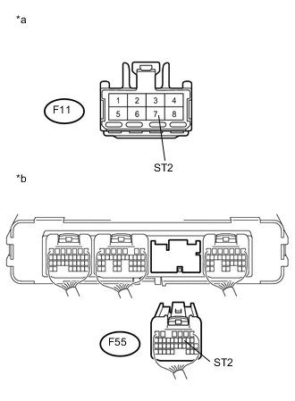
Text in Illustration *a Front view of wire harness connector
(to Ignition or Starter Switch Assembly)
*b Rear view of wire harness connector
(to Hybrid Vehicle Control ECU)
Measure the voltage according to the value(s) in the table below.
Standard Voltage Tester Connection Switch Condition Specified Condition F11-7 (ST2) or F55-9 (ST2) - Body ground and other terminals Ignition switch off Below 1 V -
Connect the hybrid vehicle control ECU connector.
-
Connect the ignition or starter switch assembly connector.
OK
REPLACE IGNITION OR STARTER SWITCH ASSEMBLY Click here
NG
REPAIR OR REPLACE HARNESS OR CONNECTOR
-