HYBRID CONTROL SYSTEM, Diagnostic DTC:P0560-117
| DTC Code | DTC Name |
|---|---|
| P0560-117 | System Voltage |
DESCRIPTION
-
Battery power is constantly supplied to the BATT terminal of the power management control ECU to allow DTCs and freeze frame data to be retained in memory even though the ignition switch is turned off. The back-up power is supplied even when the ignition switch is off.
| DTC No. | INF Code | DTC Detection Condition | Trouble Area |
|---|---|---|---|
| P0560 | 117 | Malfunction in the power management control ECU back-up power source circuit |
|
WIRING DIAGRAM
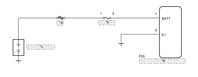
| *a | MAIN |
| *b | ECU-B NO.2 |
| *c | Auxiliary Battery |
| *d | Power Management Control ECU |
CAUTION / NOTICE / HINT
Tech Tips
After the repair, clear the DTCs and perform the following procedure to check that DTCs are not output.
-
Turn the ignition switch to ON (IG) and wait for a few seconds.
PROCEDURE
-
CHECK CONNECTOR CONNECTION CONDITION (POWER MANAGEMENT CONTROL ECU CONNECTOR)
-
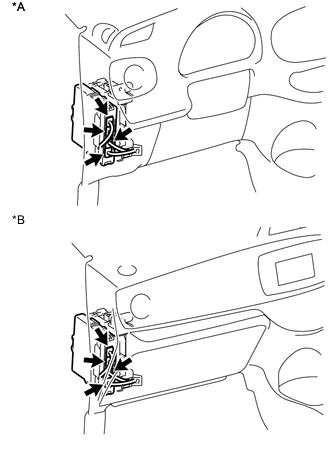
Text in Illustration *A for LHD *B for RHD Check the connector connections and contact pressure of the relevant terminals for the power management control ECU connectors Click here.
OK The connectors are connected securely and there are no contact pressure problems.
NG 
CONNECT SECURELY
OK 
-
-
CHECK AUXILIARY BATTERY TERMINAL (CONTACT PROBLEM)
-
Check the connection of the auxiliary battery terminal.
OK The terminal is connected securely and there is no contact problem.
NG
CONNECT SECURELY
OK
-
-
INSPECT AUXILIARY BATTERY
NG
CHARGE OR REPLACE AUXILIARY BATTERY
OK
-
CHECK FUSE (ECU-B NO. 2)
-
Remove the ECU-B NO. 2 fuse from the No. 2 engine room relay block.
-
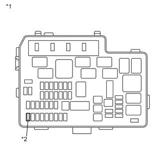
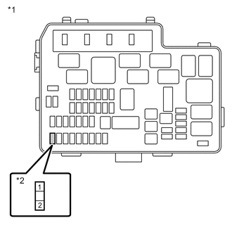
Text in Illustration *1 No. 2 Engine Room Relay Block *2 ECU-B NO. 2 Fuse Measure the resistance according to the value(s) in the table below.
Standard Resistance Tester Connection Switch Condition Specified Condition ECU-B NO. 2 fuse Ignition switch off Below 1 Ω -
Install the ECU-B NO. 2 fuse.
NG
REPLACE FUSE (ECU-B NO. 2)
OK
-
-
CHECK HARNESS AND CONNECTOR (POWER MANAGEMENT CONTROL ECU - ECU-B NO. 2 FUSE)
-
Remove the ECU-B NO. 2 fuse from the No. 2 engine room relay block.
-
Disconnect the power management control ECU connector.
-
Measure the resistance according to the value(s) in the table below.
Note
When taking measurements with a tester, do not apply excessive force to the tester probes to avoid damaging the fuse holder or terminals.
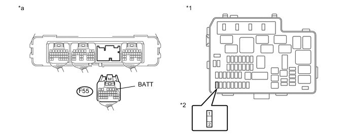
Text in Illustration *1 No. 2 Engine Room Relay Block *2 ECU-B NO. 2 Fuse *a Rear view of wire harness connector
(to Power Management Control ECU)
- - Standard Resistance (Check for Open) Tester Connection Switch Condition Specified Condition F55-1 (BATT) - 2 (ECU-B NO. 2 fuse) Ignition switch off Below 1 Ω Standard Resistance (Check for Short) Tester Connection Switch Condition Specified Condition F55-1 (BATT) or 2 (ECU-B NO. 2 fuse) - Body ground and other terminals Ignition switch off 10 kΩ or more -
Install the ECU-B NO. 2 fuse.
-
Connect the power management control ECU connector.
NG
REPAIR OR REPLACE HARNESS OR CONNECTOR
OK
-
-
CHECK HARNESS AND CONNECTOR (ECU-B NO. 2 FUSE - AUXILIARY BATTERY POSITIVE TERMINAL)
-
Disconnect the positive and negative terminals from the auxiliary battery.
-
Remove the ECU-B NO. 2 fuse from the No. 2 engine room relay block.
-
Text in Illustration *1 No. 2 Engine Room Relay Block *2 ECU-B NO. 2 Fuse Measure the resistance according to the value(s) in the table below.
Standard Resistance (Check for Open) Tester Connection Switch Condition Specified Condition 1 (ECU-B NO. 2 fuse) - Positive (+) battery terminal Ignition switch off Below 1 Ω Standard Resistance (Check for Short) Tester Connection Switch Condition Specified Condition 1 (ECU-B NO. 2 fuse) or Positive (+) battery terminal - Body ground and other terminals Ignition switch off 10 kΩ or more -
Install the ECU-B NO. 2 fuse.
-
Connect the positive and negative terminals to the auxiliary battery.
NG
REPAIR OR REPLACE HARNESS OR CONNECTOR
OK
-
-
RECONFIRM DTC OUTPUT (HYBRID CONTROL)
-
Connect the GTS to the DLC3.
-
Turn the ignition switch to ON (IG).
-
Enter the following menus: Powertrain / Hybrid Control / Trouble Codes.
-
Recheck for DTCs.
Result Result Proceed to DTC P0560-117 is output again A DTC P0560-117 is not output B Tech Tips
If DTC P0560-117 is output after this inspection, replace the power management control ECU. If the DTC is not output, check for intermittent problems Click here because there may be a malfunction in the wire harness or connector.
A
REPLACE POWER MANAGEMENT CONTROL ECU Click here
B
CHECK FOR INTERMITTENT PROBLEMS Click here
-