HYBRID CONTROL SYSTEM, Diagnostic DTC:P0516-769, P0517-770
| DTC Code | DTC Name |
|---|---|
| P0516-769 | Battery Temperature Sensor Circuit Low |
| P0517-770 | Battery Temperature Sensor Circuit High |
DESCRIPTION
-
The battery thermometer sensor detects the auxiliary battery temperature. The resistance of the battery thermometer sensor built into the thermistor changes in accordance with changes in the auxiliary battery temperature. The lower the auxiliary battery temperature, the higher the battery thermometer sensor resistance. Conversely, the higher the temperature, the lower the resistance. The battery thermometer sensor is connected to the power management control ECU. A voltage of 5 V is supplied to the battery thermometer sensor from the THB terminal of the power management control ECU through its internal resistor R. This means that resistor R and the battery thermometer sensor are connected in series. The voltage at the THB terminal and the resistance value change in accordance with changes in the auxiliary battery temperature. Based on this signal, the power management control ECU reduces the charging current when the auxiliary battery temperature is high to protect the auxiliary battery.
Tech Tips
Characteristics of the battery thermometer sensor resistance (reference values) are as follows.
Terminal THB
(with Connector Disconnected)
Resistance Ambient Temperature THB - E2 4.5 to 5.5 V 3.00 to 3.73 kΩ Approximately 10°C (50°F) 1.60 to 1.80 kΩ Approximately 25°C (77°F) 0.80 to 1.00 kΩ Approximately 40°C (104°F) 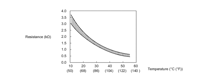
| DTC No. | INF Code | DTC Detection Condition | Trouble Area |
|---|---|---|---|
| P0516 | 769 | Malfunction in the battery thermometer sensor circuit (short to GND) |
|
| P0517 | 770 | Malfunction in the battery thermometer sensor circuit (open or short to +B) |
WIRING DIAGRAM
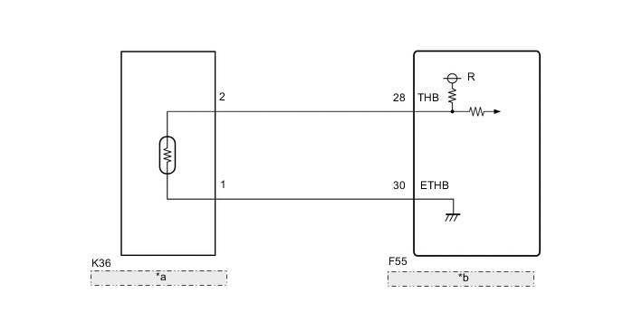
| *a | Battery Thermometer Sensor |
| *b | Power Management Control ECU |
CAUTION / NOTICE / HINT
Tech Tips
-
Read the freeze frame data using the GTS. In the freeze frame data, some information is recorded about the vehicle conditions at the moment a malfunction occurred. This information can be helpful when troubleshooting.
-
After confirming that DTC P0516-769 or P0517-770 is output, use the GTS to check "Auxiliary Batt Temperature" in the Hybrid Control Data List.
Displayed Temperature Malfunction -40°C (-40°F) Open circuit or short to +B 156°C (313°F) Short circuit or short to GND -
After the repair, clear the DTCs and perform the following procedure to check that DTCs are not output.
-
Turn the ignition switch to ON (IG) and wait for 5 seconds or more.
PROCEDURE
-
CHECK CONNECTOR CONNECTION CONDITION (POWER MANAGEMENT CONTROL ECU CONNECTOR)
-
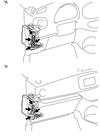
Text in Illustration *A for LHD *B for RHD Check the connector connections and contact pressure of the relevant terminals for the power management control ECU connectors Click here.
OK The connectors are connected securely and there are no contact pressure problems.
NG 
CONNECT SECURELY
OK 
-
-
READ VALUE USING GTS (AUXILIARY BATT TEMPERATURE)
-
Connect the GTS to the DLC3.
-
Turn the ignition switch to ON (IG).
-
Enter the following menus: Powertrain / Hybrid Control / Data List / Auxiliary Batt Temperature.
-
Read the Data List.
Result Result Proceed to -40°C (-40°F) A 156°C (313°F) B Same as actual temperature C -
Turn the ignition switch off.
B 
READ VALUE USING GTS (CHECK FOR SHORT) Click here
C
CHECK FOR INTERMITTENT PROBLEMS Click here
A
-
-
READ VALUE USING GTS (CHECK FOR OPEN)
-
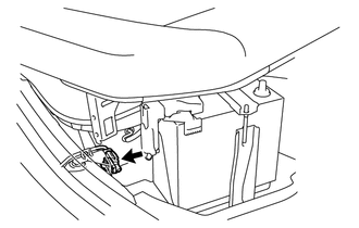
Disconnect the battery thermometer sensor connector.
-
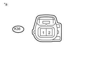
Connect terminals 2 and 1 of vehicle side connector K36 of the battery thermometer sensor.
-
Connect the GTS to the DLC3.
-
Turn the ignition switch to ON (IG).
-
Enter the following menus: Powertrain / Hybrid Control / Data List / Auxiliary Batt Temperature.
-
Read the Data List.
OK GTS Display Condition Specified Condition Auxiliary Batt Temperature Terminals 2 and 1 connected.
Ignition switch ON (IG)
156°C (313°F) Text in Illustration *a Front view of wire harness connector
(to Battery Thermometer Sensor)
-
Turn the ignition switch off.
-
Connect the battery thermometer sensor connector.
OK
REPLACE BATTERY THERMOMETER SENSOR
NG
-
-
CHECK HARNESS AND CONNECTOR (POWER MANAGEMENT CONTROL ECU - BATTERY THERMOMETER SENSOR)
-
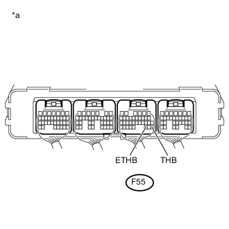
Text in Illustration *a Component with harness connected
(Power Management Control ECU)
Connect terminals 28 (THB) and 30 (ETHB) of connector F55 of the power management control ECU.
-
Connect the GTS to the DLC3.
-
Turn the ignition switch to ON (IG).
-
Enter the following menus: Powertrain / Hybrid Control / Data List / Auxiliary Batt Temperature.
-
Read the Data List.
OK GTS Display Condition Specified Condition Auxiliary Batt Temperature Terminals THB and ETHB connected.
Ignition switch ON (IG)
156°C (313°F) -
Turn the ignition switch off.
OK
REPAIR OR REPLACE HARNESS OR CONNECTOR
NG
REPLACE POWER MANAGEMENT CONTROL ECU Click here
-
-
READ VALUE USING GTS (CHECK FOR SHORT)
-
Disconnect connector K36 from the battery thermometer sensor.
-
Connect the GTS to the DLC3.
-
Turn the ignition switch to ON (IG).
-
Enter the following menus: Powertrain / Hybrid Control / Data List / Auxiliary Batt Temperature.
-
Read the Data List.
OK GTS Display Switch Condition Specified Condition Auxiliary Batt Temperature Ignition switch ON (IG) -40°C (-40°F) -
Turn the ignition switch off.
-
Connect the battery thermometer sensor connector.
OK
REPLACE BATTERY THERMOMETER SENSOR
NG
-
-
CHECK HARNESS AND CONNECTOR (BATTERY THERMOMETER SENSOR - POWER MANAGEMENT CONTROL ECU)
-
Disconnect the battery thermometer sensor connector.
-
Disconnect the power management control ECU connector.
-
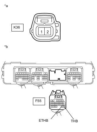
Text in Illustration *a Front view of wire harness connector
(to Battery Thermometer Sensor)
*b Rear view of wire harness connector
(to Power Management Control ECU)
Measure the resistance according to the value(s) in the table below.
Standard Resistance (Check for Open) Tester Connection Switch Condition Specified Condition K36-2 - F55-28 (THB) Ignition switch off Below 1 Ω K36-1 (E2) - F55-30 (ETHB) Ignition switch off Below 1 Ω Standard Resistance (Check for Short) Tester Connection Switch Condition Specified Condition K36-2 or F55-28 (THB)- Body ground and other terminals Ignition switch off 10 kΩ or higher K36-1 or F55-30 (ETHB)- Body ground and other terminals Ignition switch off 10 kΩ or higher -
Connect the battery thermometer sensor connector.
-
Connect the power management control ECU connector.
OK
REPLACE POWER MANAGEMENT CONTROL ECU Click here
NG
REPAIR OR REPLACE HARNESS OR CONNECTOR
-