HYBRID CONTROL SYSTEM, Diagnostic DTC:P0069-273
| DTC Code | DTC Name |
|---|---|
| P0069-273 | Manifold Absolute Pressure - Barometric Pressure Correlation |
DESCRIPTION
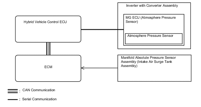
The atmospheric pressure sensor mounted on the MG ECU circuit board detects the atmospheric pressure. This reading is used to perform system control that considers vehicle usage conditions.
| DTC No. | INF Code | DTC Detection Condition | Trouble Area |
|---|---|---|---|
| P0069 | 273 | Difference between the atmospheric pressure value of the atmosphere pressure sensor in the inverter with converter assembly and the manifold absolute pressure sensor assembly exceeds a specified value and the same condition recurs after 3 hours or more when driving in EV drive mode. (1 trip detection logic) |
|
| DTC No. | Data List |
|---|---|
| P0069-273 |
|
WIRING DIAGRAM

CAUTION / NOTICE / HINT
Tech Tips
After the repair, perform the following procedure to confirm the repair.
-
If the values of Data List items "Atmosphere Pressure" and "MAP" are almost the same with the engine stopped and the ignition switch to ON (IG), the vehicle is normal.
PROCEDURE
-
CHECK DTC OUTPUT (ENGINE AND ECT)
-
Connect the GTS to the DLC3.
-
Turn the ignition switch to ON (READY).
-
Fully depress the accelerator pedal for 5 seconds to start the engine and keep it running.
-
Enter the following menus: Powertrain / Engine and ECT / Trouble Codes.
-
Check if DTCs are output.
Result Result Proceed to Except the following. A Any of the following DTCs are also output. B DTC No. Relevant Diagnosis P0107 Manifold Absolute Pressure / Barometric Pressure Circuit Low Input P0108 Manifold Absolute Pressure / Barometric Pressure Circuit High Input P106A Evaporative Emission System Pressure Sensor - Manifold Absolute Pressure Correlation Tech Tips
P0069-273 may be output due to a malfunction which causes the DTCs in the preceding table to be output. In this case, first troubleshoot the output DTCs in the preceding table.
-
Turn the ignition switch off.
B 
GO TO DTC CHART (SFI SYSTEM) Click here
A 
-
-
CHECK DTC OUTPUT (HYBRID CONTROL)
-
Connect the GTS to the DLC3.
-
Turn the ignition switch to ON (IG).
-
Enter the following menus: Powertrain / Hybrid Control / Trouble Codes.
-
Check if DTCs are output.
Result Result Proceed to P0069-273 only is output or DTCs except the ones in the table below are also output. A Any of the following DTCs are also output. B DTC No. Relevant Diagnosis P0A1A-151, 658 Generator Control Module P0A1B-786 Drive Motor "A" Control Module P0A1D-148 Hybrid Powertrain Control Module P1C2A-155 Generator A/D Converter Circuit P1C73-512 Sensor Standard Voltage "F" Circuit / Open P1CA6-156 Generator Control Module Malfunction P1CA7-193 Drive Motor Control Module Malfunction P2228-268 Barometric Pressure Sensor "A" Circuit Low P2229-269 Barometric Pressure Sensor "A" Circuit High P2511-149 ECM/PCM Power Relay Sensor Circuit Intermittent P3133-659 Communication Error from Generator to Drive Motor "A" P3134-661 Communication Error from Drive Motor "A" to Generator P324E-788 MG-ECU Power Relay Intermittent Circuit U0100-211, 530 Lost Communication with ECM/PCM "A" U0110 (all INF codes)*1 Lost Communication with Drive Motor Control Module "A" Tech Tips
-
*1: If any INF codes are output for this DTC, refer to the corresponding diagnostic procedure.
-
P0069-273 may be output due to a malfunction which causes the DTCs in the preceding table to be output. In this case, first troubleshoot the output DTCs in the preceding table.
-
-
Turn the ignition switch off.
B
GO TO DTC CHART (HYBRID CONTROL SYSTEM) Click here
A
-
-
READ VALUE USING GTS (MAP, ATMOSPHERE PRESSURE)
-
Connect the GTS to the DLC3.
-
Turn the ignition switch to ON (IG).
-
Enter the following menus: Powertrain / Hybrid Control / Data List / MAP, Atmosphere Pressure.
-
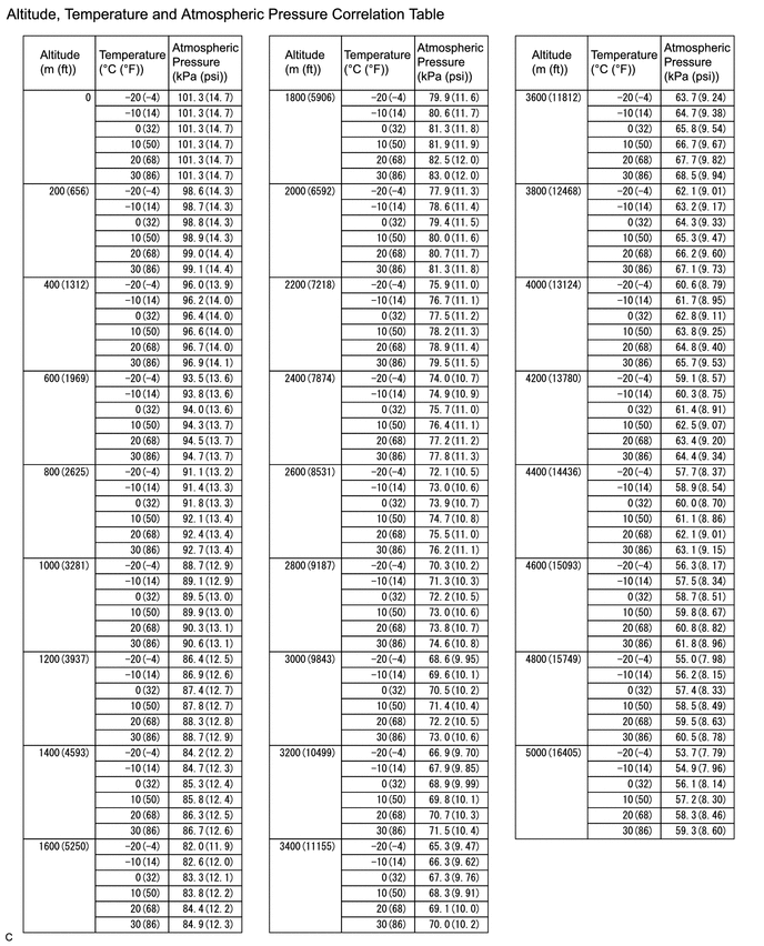
Using the table, read the normal atmospheric pressure value for the applicable altitude.
Tech Tips
-
Standard atmospheric pressure is approximately 101 kPa.
-
For every 100 m (328 ft) increase in altitude, atmospheric pressure drops by approximately 1 kPa (7.5 mmHg).
-
The actual atmospheric pressure also varies by weather.
-
-
Compare the MAP and Atmosphere Pressure values in the Data List with the normal atmospheric value from the table.
Result Result Proceed to Other than the following. A Difference between MAP in Data List and "normal atmospheric pressure value" is 10 kPa or more. B Difference between Atmosphere Pressure in Data List and "normal atmospheric pressure value" is 10 kPa or more. C -
Turn the ignition switch off.
B 
REPLACE MANIFOLD ABSOLUTE PRESSURE SENSOR Click here
C
REFER TO REPLACE INVERTER WITH CONVERTER ASSEMBLY PARTS Click here
A
-
-
READ VALUE USING GTS (MAP)
-
Move the shift lever to P.
-
Enter the following menus: Powertrain / Hybrid Control / Data List / MAP
-
Read the MAP value in the Data List with the engine stopped.
-
While depressing the brake pedal, Turn the ignition switch to ON (READY).
-
With the READY indicator light illuminated, fully depress the accelerator pedal.
-
Read the MAP value in the Data List with the engine running.
-
Compare the MAP value noted with the engine stopped and the MAP value noted with the engine running.
OK The MAP value changes (pressure decreases when the engine is started). -
Turn the ignition switch off.
NG
CHECK TERMINAL VOLTAGE (POWER SOURCE OF MANIFOLD ABSOLUTE PRESSURE SENSOR) Click here
OK
-
-
REPLACE MANIFOLD ABSOLUTE PRESSURE SENSOR
NEXT
-
READ VALUE USING GTS (MAP, ATMOSPHERE PRESSURE)
-
Connect the GTS to the DLC3.
-
Turn the ignition switch to ON (IG).
-
Enter the following menus: Powertrain / Hybrid Control / Data List / MAP, Atmosphere Pressure.
-
Compare the Data List item "MAP" with "Atmosphere Pressure".
Result Result Proceed to The difference between "MAP" and "Atmosphere Pressure" is 10 kPa or more. A The difference between "MAP" and "Atmosphere Pressure" is less than 10 kPa. B -
Turn the ignition switch off.
A
REFER TO REPLACE INVERTER WITH CONVERTER ASSEMBLY PARTS Click here
B
COMPLETED
-
-
CHECK TERMINAL VOLTAGE (POWER SOURCE OF MANIFOLD ABSOLUTE PRESSURE SENSOR)
-
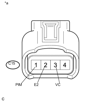
Text in Illustration *a Front view of wire harness connector
(to Manifold Absolute Pressure Sensor)
Disconnect the manifold absolute pressure sensor connector.
-
Turn the ignition switch to ON (IG).
-
Measure the voltage according to the value(s) in the table below.
Standard Voltage Tester Connection Condition Specified Condition C15-3 (VC) - C15-2 (E2) Ignition switch ON (IG) 4.75 to 5.25 V C15-1 (PIM) - C15-2 (E2) Ignition switch ON (IG) 3.0 to 5.0 V
NG
CHECK HARNESS AND CONNECTOR (MANIFOLD ABSOLUTE PRESSURE SENSOR - ECM) Click here
OK
-
-
REPLACE MANIFOLD ABSOLUTE PRESSURE SENSOR
NEXT
-
CLEAR DTC
-
Connect the GTS to the DLC3.
-
Turn the ignition switch to ON (IG).
-
Enter the following menus: Powertrain / Hybrid Control / Trouble Codes.
-
Clear DTCs and freeze frame data.
-
Turn the ignition switch off.
NEXT
-
-
READ VALUE USING GTS (MAP, ATMOSPHERE PRESSURE)
-
Connect the GTS to the DLC3.
-
Turn the ignition switch to ON (IG).
-
Enter the following menus: Powertrain / Hybrid Control / Data List / MAP, Atmosphere Pressure.
-
Compare the Data List item "MAP" with "Atmosphere Pressure".
Result Result Proceed to The difference between "MAP" and "Atmosphere Pressure" is less than 10 kPa. A The difference between "MAP" and "Atmosphere Pressure" is 10 kPa or more. B -
Turn the ignition switch off.
A
END
B
REPLACE ECM Click here
-
-
CHECK HARNESS AND CONNECTOR (MANIFOLD ABSOLUTE PRESSURE SENSOR - ECM)
-
Disconnect the C15 manifold absolute pressure sensor connector.
-
Disconnect the C10 ECM connector (for LHD).
-
Disconnect the C9 ECM connector (for RHD).
-
Measure the resistance according to the value(s) in the table below.
Standard Resistance for LHD Tester Connection Condition Specified Condition C15-3 (VC) - C10-118 (VCPM) Always Below 1 Ω C15-2 (E2) - C10-119 (EPIM) Always Below 1 Ω C15-1 (PIM) - C10-87 (PIM) Always Below 1 Ω C15-3 (VC) or C10-118 (VCPM) - Body ground Always 10 kΩ or higher C15-1 (PIM) or C10-87 (PIM) - Body ground Always 10 kΩ or higher for RHD Tester Connection Condition Specified Condition C15-3 (VC) - C9-118 (VCPM) Always Below 1 Ω C15-2 (E2) - C9-119 (EPIM) Always Below 1 Ω C15-1 (PIM) - C9-87 (PIM) Always Below 1 Ω C15-3 (VC) or C9-118 (VCPM) - Body ground Always 10 kΩ or higher C15-1 (PIM) or C9-87 (PIM) - Body ground Always 10 kΩ or higher
OK
REPLACE ECM Click here
NG
REPAIR OR REPLACE HARNESS OR CONNECTOR
-