FRONT DOOR WINDOW FRAME MOULDING REMOVAL

-
REMOVE REAR DECK FLOOR BOX
-

Remove the 3 clips and the rear deck floor box.
-
-
PRECAUTION (w/ Navigation System for HDD)
Note
After the power switch is turned off, the display and navigation module display (HDD navigation system) records various types of memory and settings. As a result, after turning the power switch off, make sure to wait for the time specified in the following table before disconnecting the cable from the negative (-) battery terminal.
Waiting Time before Disconnecting Cable from Negative (-) Battery Terminal Specification Waiting Time w/o Telematics transceiver 60 sec. w/ Telematics transceiver 120 sec. -
DISCONNECT CABLE FROM NEGATIVE BATTERY TERMINAL
CAUTION:
Wait at least 90 seconds after disconnecting the cable from the negative (-) battery terminal to disable the SRS system.
Note
When disconnecting the cable, some systems need to be initialized after the cable is reconnected Click here.
-
REMOVE FRONT DOOR INSIDE HANDLE BEZEL PLUG
-
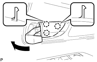
Using a moulding remover, disengage the 3 claws and remove the front door inside handle bezel plug as shown in the illustration.
-
-
REMOVE POWER WINDOW REGULATOR MASTER SWITCH ASSEMBLY WITH FRONT DOOR ARMREST BASE PANEL (for Driver Side)
-
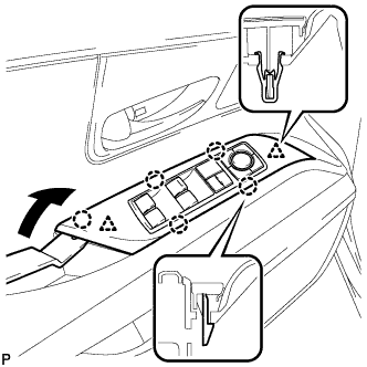
Using a moulding remover, disengage the 2 clips and 5 claws as shown in the illustration.
-
Disconnect the connector and remove the power window regulator master switch assembly with front door armrest base panel.
-
-
REMOVE POWER WINDOW REGULATOR SWITCH ASSEMBLY WITH FRONT DOOR ARMREST BASE PANEL (for Front Passenger Side)
-
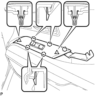
Using a moulding remover, disengage the 2 clips and 5 claws.
-
Disconnect the connector and remove the power window regulator switch assembly with front door armrest base panel.
-
-
REMOVE DOOR ARMREST COVER
-
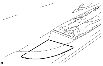
Remove the door armrest cover.
-
-
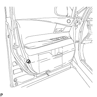
REMOVE COURTESY LIGHT ASSEMBLY
-

Using a screwdriver wrapped with protective tape, disengage the claw.
-
Disconnect the connector and remove the courtesy light assembly.
-
-
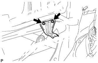
REMOVE NO. 1 FRONT DOOR STIFFENER CUSHION
-
Remove the screw and No. 1 front door stiffener cushion.
-
-
REMOVE FRONT DOOR TRIM BOARD SUB-ASSEMBLY
-
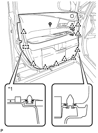
Remove the 3 screws.
-
Using a clip remover, disengage the 10 clips and front door trim board retainer.
Text in Illustration *1 Front Door Trim Board Retainer -
Pull out the front door trim board sub-assembly in the direction indicated by the arrow as shown in the illustration.
-
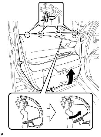
Raise the front door trim board sub-assembly to disengage the 4 claws and remove the front door trim board sub-assembly together with the front door inner glass weatherstrip.
-
Disconnect each connector.
-
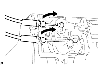
Disconnect the front door lock remote control cable assembly and front door inside locking cable assembly.
-
Remove the front door trim board retainer (green) from the front door trim board sub-assembly.
-
-
REMOVE FRONT DOOR INNER GLASS WEATHERSTRIP
-
Using a moulding remover, disengage the 4 claws and remove the front door inner glass weatherstrip from the front door trim board sub-assembly as shown in the illustration.
-
-
REMOVE DOOR FRAME GARNISH
-
Remove the 2 clips and door frame garnish.
-
-
REMOVE FRONT NO. 3 SPEAKER ASSEMBLY
-
Disconnect the connector.
-
Remove the 2 screws.
-
Disengage the clip and remove the front No. 3 speaker assembly.
-
-
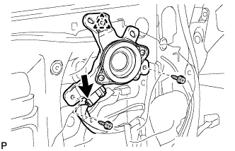
REMOVE OUTER MIRROR CONTROL ECU ASSEMBLY
-
Disconnect each connector.
-
Remove the 2 screws and the outer mirror control ECU assembly.
-
-
REMOVE NO. 1 FRONT DOOR TRIM BRACKET
-
Remove the 2 screws and No. 1 front door trim bracket.
-
-
REMOVE FRONT DOOR SERVICE HOLE COVER
-
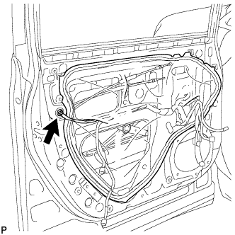
Disconnect the connector.
-
Remove the front door service hole cover.
Tech Tips
Remove any remaining butyl tape from the door.
-
-
REMOVE FRONT DOOR GLASS SUB-ASSEMBLY
-
Connect the cable to the negative (-) battery terminal.
-
Connect the power window regulator master switch assembly and move the front door glass sub-assembly so that the door glass bolts can be seen.
-
w/ Navigation System for HDD:
Note
After the power switch is turned off, the display and navigation module display (HDD navigation system) records various types of memory and settings. As a result, after turning the power switch off, make sure to wait for the time specified in the following table before disconnecting the cable from the negative (-) battery terminal.
Waiting Time before Disconnecting Cable from Negative (-) Battery Terminal Specification Waiting Time w/o Telematics transceiver 60 sec. w/ Telematics transceiver 120 sec.
-
-
Disconnect the cable from the negative (-) battery terminal and power window regulator master switch assembly.
CAUTION:
Wait at least 90 seconds after disconnecting the cable from the negative (-) battery terminal to disable the SRS system Click here.
-
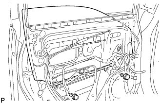
Remove the 2 bolts.
Note
After the bolts are removed, do not allow the door glass to fall.
-
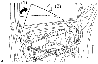
Remove the front door glass sub-assembly as indicated by the arrows in the order shown in the illustration.
Note
Do not damage the door glass.
-
-
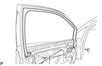
REMOVE FRONT DOOR GLASS RUN
-
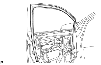
Remove the front door glass run.
-
-
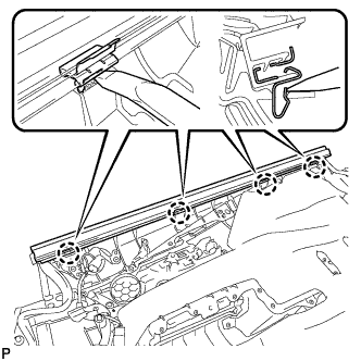
REMOVE FRONT DOOR BELT MOULDING ASSEMBLY
-
Text in Illustration *1 Protective Tape Put protective tape around the front door belt moulding assembly.
-
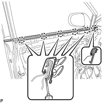
Using a screwdriver, disengage the 6 claws and remove the front door belt moulding assembly.
-
-
DISCONNECT FRONT DOOR WEATHERSTRIP
-
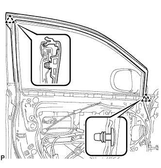
Using a clip remover, disengage the 2 clips and remove the upper part of the front door weatherstrip to the extent that allows removal of the front door window frame moulding.
-
-
REMOVE FRONT DOOR REAR WINDOW FRAME MOULDING
Tech Tips
When removing the front door rear window frame moulding, heat the vehicle body and front door rear window frame moulding using a heat light.
Heating Temperature Item Temperature Vehicle Body 40 to 60°C (104 to 140°F) Moulding 20 to 30°C (68 to 86°F) Note
Do not heat the vehicle body or moulding excessively.
-
Using a heat light, heat the front door rear window frame moulding.
-
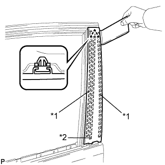
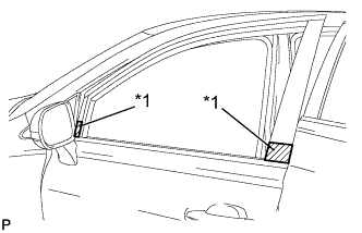
Text in Illustration *1 Double-sided Tape *2 Caulking Sponge Using a moulding remover, remove the clip and front door rear window frame moulding.
-
-
REMOVE FRONT DOOR SCUFF PLATE
-
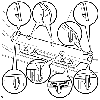
Disengage the 7 claws, 4 clips and guide, and remove the front door scuff plate LH.
Tech Tips
A part of the clip remains on the vehicle side.
-
w/ Illumination:
-
Disconnect the connector.
-
-
-
REMOVE COWL SIDE TRIM SUB-ASSEMBLY
-
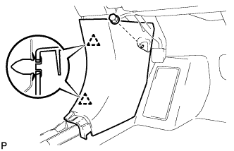
Remove the clip.
-
Disengage the 2 clips and remove the cowl side trim sub-assembly LH.
-
-
REMOVE FRONT DOOR CHECK COVER
-
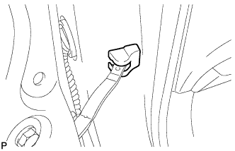
Remove the front door check cover.
-
-
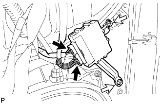
REMOVE FRONT DOOR PANEL SUB-ASSEMBLY
-
Disconnect each connector.
-
Disengage each clamp.
-
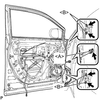
Remove the bolt <A> and disengage the front door check assembly.
-
Remove the 4 bolts <B> and front door panel sub-assembly.
Note
To prevent damage, when removing the front door panel sub-assembly, make sure that there are enough people available to hold it securely.
-
-
REMOVE FRONT DOOR UPPER WINDOW FRAME MOULDING
-
Insert a 4.0 mm (0.157 in.) drill bit into a drill.
-
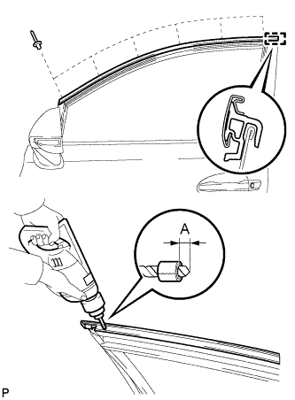
Tape the 4.0 mm (0.157 in.) drill bit 5.0 mm (0.197 in.) from the tip as shown in the illustration.
Area Dimension A 5.0 mm (0.197 in.) Note
Tape the 4.0 mm (0.157 in.) drill bit to prevent the drill bit from going too deep.
-
Lightly press the drill against the rivets to drill off the rivet flanges, and remove the 6 rivets.
Note
-
Pressing the drill too firmly will cause the rivet to turn and result in the rivet not being drilled through.
-
Prying the rivets with the drill may damage the rivet installation holes or drill bit.
-
Be careful of the drilled rivets, as they may be hot.
-
-
Using a vacuum cleaner, remove the rivet fragments and shavings from the drilled areas.
-
Disengage the guide and remove the front door upper window frame moulding from the door frame.
-
-
REMOVE FRONT DOOR FRONT WINDOW FRAME MOULDING
-
Insert a 4.0 mm (0.157 in.) drill bit into a drill.
-
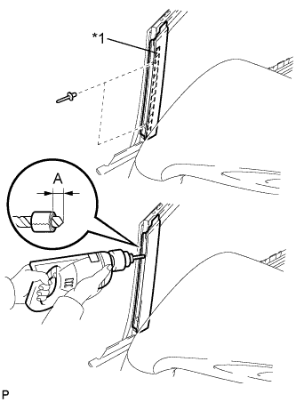
Text in Illustration *1 Caulking Sponge Tape the 4.0 mm (0.157 in.) drill bit 5.0 mm (0.197 in.) from the tip as shown in the illustration.
Area Dimension A 5.0 mm (0.197 in.) Note
Tape the 4.0 mm (0.157 in.) drill bit to prevent the drill bit from going too deep.
-
Lightly press the drill against the rivets to drill off the rivet flanges, and remove the 2 rivets.
Note
-
Pressing the drill too firmly will cause the rivet to turn and result in the rivet not being drilled through.
-
Prying the rivets with the drill may damage the rivet installation holes or drill bit.
-
Be careful of the drilled rivets, as they may be hot.
-
-
Using a vacuum cleaner, remove the rivet fragments and shavings from the drilled areas.
-
Disengage the guide and remove the front door front window frame moulding from the door frame.
-