STOP LIGHT SWITCH INSTALLATION

-
INSTALL STOP LIGHT SWITCH ASSEMBLY
-
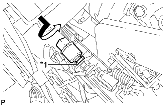
Text in Illustration *1 Lock Nut Temporarily install the stop light switch assembly with the stop light switch lock nut.
-
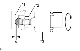
Text in Illustration *1 Cushion *2 Stop Light Switch Lock Nut *3 Stop Light Switch Turn the stop light switch assembly so that the clearance between the nut end and stop light switch cushion is between A.
Standard Clearance Area Measurement A 0.5 to 2.4 mm (0.0197 to 0.0945 in.) -
Tighten the stop light switch lock nut.
- Torque:
- 17 N*m { 170 kgf*cm, 12 ft.*lbf }
-
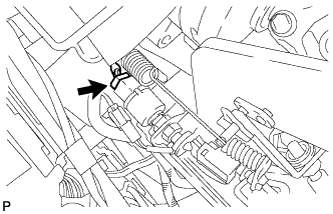
Connect the connector.
-
-
INSTALL NO. 1 INSTRUMENT PANEL UNDER COVER SUB-ASSEMBLY (for LHD)
-
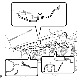
Engage each clamp.
-
Connect each connector.
-
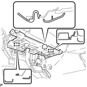
Engage the claw and 2 guides.
-

Install the No. 1 instrument panel under cover sub- assembly with the 2 screws <D>.
-
-
INSTALL NO. 1 INSTRUMENT PANEL UNDER COVER SUB-ASSEMBLY (for RHD)
-
Engage each clamp.
-
Connect each connector.
-
Engage the claw and 2 guides.
-
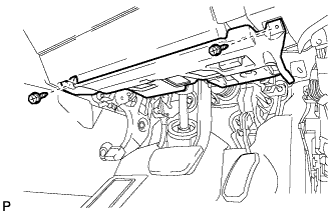
Install the No. 1 instrument panel under cover sub- assembly with the 2 screws <D>.
-