LIGHTING SYSTEM Low Beam Headlight Circuit
DESCRIPTION
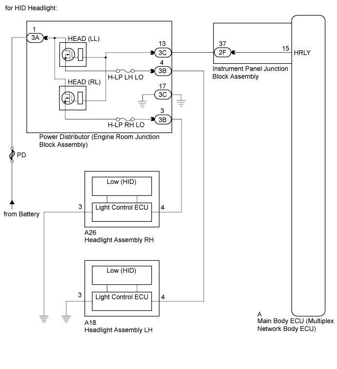
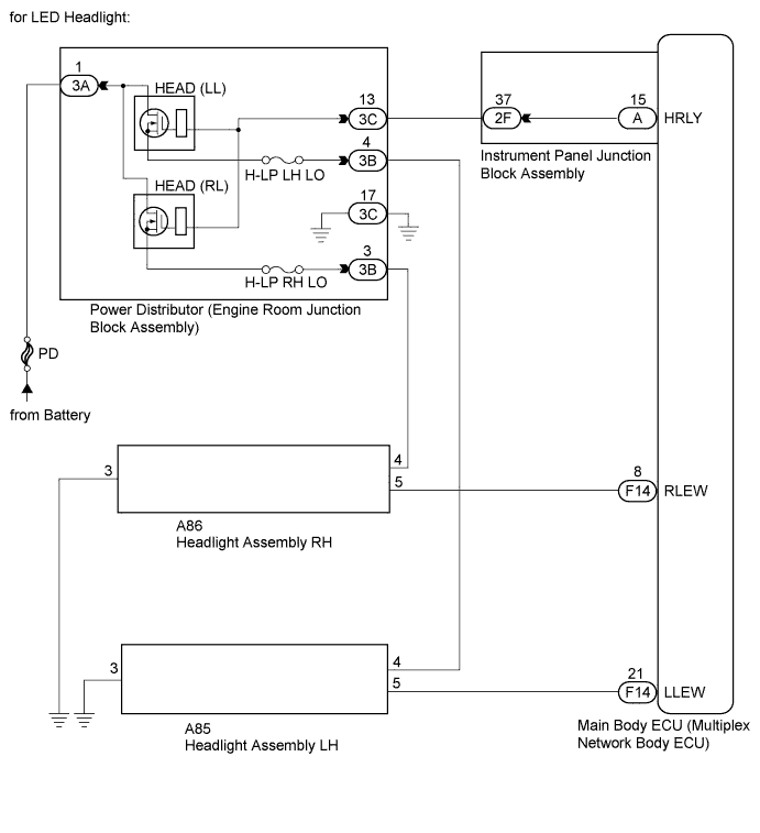
The main body ECU (multiplex network body ECU) controls the headlight relays.
WIRING DIAGRAM
INSPECTION PROCEDURE
Note
Inspect the fuses for circuits related to this system before performing the following inspection procedure.
PROCEDURE
-
PERFORM ACTIVE TEST USING INTELLIGENT TESTER
-
Connect the intelligent tester to the DLC3.
-
Turn the power switch on (IG).
-
Turn the intelligent tester on.
-
Enter the following menus: Body / Main Body / Active Test.
-
Check that the relays operate.
Main Body Tester Display Test Part Control Range Diagnostic Note Headlight Relay Headlight relays ON/OFF - OK Headlight relays operate. (Low beam headlights illuminate.)
NG 
INSPECT POWER DISTRIBUTOR ENGINE ROOM JUNCTION BLOCK ASSEMBLY Click here
OK 
PROCEED TO NEXT SUSPECTED AREA SHOWN IN PROBLEM SYMPTOMS TABLE Click here
-
-
INSPECT POWER DISTRIBUTOR ENGINE ROOM JUNCTION BLOCK ASSEMBLY
-
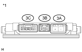
Text in Illustration *1 Component without harness connected
(Power Distributor (Engine Room Junction Block Assembly))
Remove the power distributor (engine room junction block assembly) from the engine room relay block Click here.
-
Connect a positive (+) lead from the battery to terminal 3A-1.
-
Connect a negative (-) lead from the battery to terminals 3C-13 and 3C-17.
-
Measure the voltage according to the value(s) in the table below.
Standard Voltage Tester Connection Condition Specified Condition 3B-3 - Battery negative Always 11 to 14 V 3B-4 - Battery negative Always 11 to 14 V
NG 
REPLACE POWER DISTRIBUTOR (ENGINE ROOM JUNCTION BLOCK ASSEMBLY) Click here
OK 
-
-
CHECK HARNESS AND CONNECTOR (BATTERY - POWER DISTRIBUTOR)
-
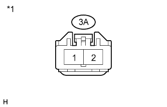
Text in Illustration *1 Front view of wire harness connector
(to Power Distributor (Engine Room Junction Block Assembly))
Disconnect the 3A power distributor (engine room junction block assembly) connector.
-
Measure the voltage according to the value(s) in the table below.
Standard Voltage Tester Connector Condition Specified Condition 3A-1 - Body ground Always 11 to 14 V
NG
REPAIR OR REPLACE HARNESS OR CONNECTOR
OK
-
-
CHECK HARNESS AND CONNECTOR (POWER DISTRIBUTOR - BODY GROUND)
-
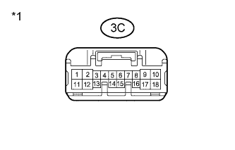
Text in Illustration *1 Front view of wire harness connector
(to Power Distributor (Engine Room Junction Block Assembly))
Disconnect the 3C power distributor (engine room junction block assembly) connector.
-
Measure the resistance according to the value(s) in the table below.
Standard Resistance Tester Connection Condition Specified Condition 3C-17 - Body ground Always Below 1 Ω
NG
REPAIR OR REPLACE HARNESS OR CONNECTOR
OK
-
-
CHECK HARNESS AND CONNECTOR (POWER DISTRIBUTOR - INSTRUMENT PANEL JUNCTION BLOCK ASSEMBLY)
-
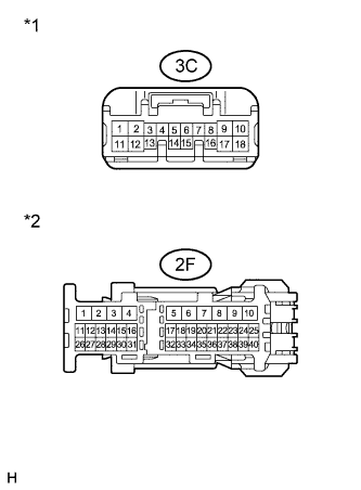
Text in Illustration *1 Front view of wire harness connector
(to Power Distributor (Engine Room Junction Block Assembly))
*2 Front view of wire harness connector
(to Instrument Panel Junction Block Assembly)
Disconnect the 3C power distributor (engine room junction block assembly) connector.
-
Disconnect the 2F instrument panel junction block assembly connector.
-
Measure the resistance according to the value(s) in the table below.
Standard Resistance Tester Connection Condition Specified Condition 3C-13 - 2F-37 Always Below 1 Ω 3C-13 - Body ground Always 10 kΩ or higher
NG
REPAIR OR REPLACE HARNESS OR CONNECTOR
OK
-
-
INSPECT INSTRUMENT PANEL JUNCTION BLOCK ASSEMBLY
-
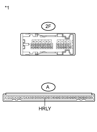
Text in Illustration *1 Component without harness connected
(Instrument Panel Junction Block Assembly)
Remove the instrument panel junction block assembly.
-
Measure the resistance according to the value(s) in the table below.
Standard Resistance Tester Connection Condition Specified Condition 2F-37 - A-15 (HRLY) Always Below 1 Ω 2F-37 - Body ground Always 10 kΩ or higher
NG
REPLACE INSTRUMENT PANEL JUNCTION BLOCK ASSEMBLY
OK
REPLACE MAIN BODY ECU (MULTIPLEX NETWORK BODY ECU) Click here
-