LIGHTING SYSTEM, Diagnostic DTC:B2430, B2431

| DTC Code | DTC Name |
|---|---|
| B2430 | LED Headlight LH Circuit Malfunction |
| B2431 | LED Headlight RH Circuit Malfunction |
DESCRIPTION
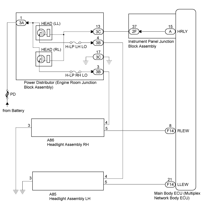
These DTCs are stored when the low beam headlights do not illuminate, or a malfunction is detected in the communication between the headlight assembly and the main body ECU (multiplex network body ECU).
| DTC Code | DTC Detection Condition | Trouble Area |
|---|---|---|
| B2430 | LED headlight LH circuit malfunction |
|
| B2431 | LED headlight RH circuit malfunction |
|
WIRING DIAGRAM
INSPECTION PROCEDURE
Note
Inspect the fuses for circuits related to this system before performing the following inspection procedure.
PROCEDURE
-
CHECK FOR DTC
-
Clear the DTCs Click here.
-
Check for DTCs Click here.
Result Result Proceed to Both DTC B2430 and DTC B2431 are not output. A Both DTC B2430 and DTC B2431 are output. B DTC B2430 or B2431 is output. C
B 
INSPECT POWER DISTRIBUTOR (ENGINE ROOM JUNCTION BLOCK ASSEMBLY) Click here
C
INSPECT HEADLIGHT ASSEMBLY Click here
A 
USE SIMULATION METHOD TO CHECK
-
-
INSPECT POWER DISTRIBUTOR (ENGINE ROOM JUNCTION BLOCK ASSEMBLY)
-
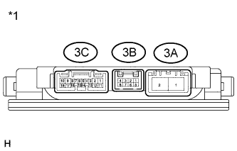
Text in Illustration *1 Component without harness connected
(Power Distributor (Engine Room Junction Block Assembly))
Remove the power distributor (engine room junction block assembly) from the engine room relay block Click here.
-
Connect a positive (+) lead from the battery to terminal 3A-1
-
Connect a negative (-) lead from the battery to terminals 3C-13 and 3C-17.
-
Measure the voltage according to the value(s) in the table below.
Standard Voltage Tester Connection Condition Specified Condition 3B-3 - Battery negative Always 11 to 14 V 3B-4 - Battery negative Always 11 to 14 V
NG 
REPLACE POWER DISTRIBUTOR (ENGINE ROOM JUNCTION BLOCK ASSEMBLY) Click here
OK 
-
-
CHECK HARNESS AND CONNECTOR (POWER DISTRIBUTOR - BATTERY AND BODY GROUND)
-
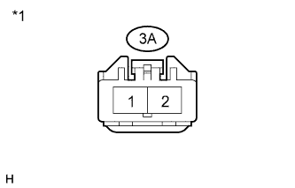
Text in Illustration *1 Front view of wire harness connector
(to Power Distributor (Engine Room Junction Block Assembly))
Disconnect the 3A power distributor (engine room junction block assembly) connector.
-
Measure the voltage according to the value(s) in the table below.
Standard Voltage Tester Connector Condition Specified Condition 3A-1 - Body ground Always 11 to 14 V -
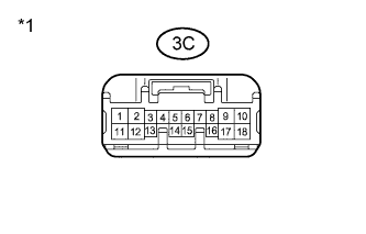
Text in Illustration *1 Front view of wire harness connector
(to Power Distributor (Engine Room Junction Block Assembly))
Disconnect the 3C power distributor (engine room junction block assembly) connector.
-
Measure the resistance according to the value(s) in the table below.
Standard Resistance Tester Connection Condition Specified Condition 3C-17 - Body ground Always Below 1 Ω
NG
REPAIR OR REPLACE HARNESS OR CONNECTOR
OK
-
-
CHECK HARNESS AND CONNECTOR (POWER DISTRIBUTOR - INSTRUMENT PANEL JUNCTION BLOCK ASSEMBLY)
-
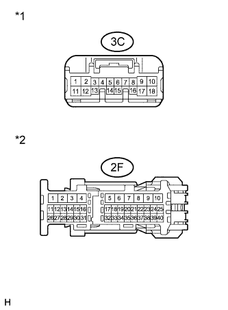
Text in Illustration *1 Front view of wire harness connector
(to Power Distributor (Engine Room Junction Block Assembly))
*2 Front view of wire harness connector
(to Instrument Panel Junction Block Assembly)
Disconnect the 3C power distributor (engine room junction block assembly) connector.
-
Disconnect the 2F instrument panel junction block assembly connector.
-
Measure the resistance according to the value(s) in the table below.
Standard Resistance Tester Connection Condition Specified Condition 3C-13 - 2F-37 Always Below 1 Ω 3C-13 - Body ground Always 10 kΩ or higher
NG
REPAIR OR REPLACE HARNESS OR CONNECTOR
OK
-
-
INSPECT INSTRUMENT PANEL JUNCTION BLOCK ASSEMBLY
-
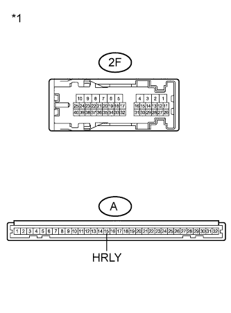
Text in Illustration *1 Component without harness connected
(Instrument Panel Junction Block Assembly)
Remove the instrument panel junction block assembly.
-
Measure the resistance according to the value(s) in the table below.
Standard Resistance Tester Connection Condition Specified Condition 2F-37 - A-15 (HRLY) Always Below 1 Ω 2F-37 - Body ground Always 10 kΩ or higher
NG
REPLACE INSTRUMENT PANEL JUNCTION BLOCK ASSEMBLY
OK
REPLACE MAIN BODY ECU (MULTIPLEX NETWORK BODY ECU) Click here
-
-
INSPECT HEADLIGHT ASSEMBLY
-
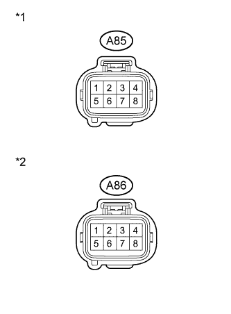
Text in Illustration *1 Front view of wire harness connector
(to Headlight Assembly LH)
*2 Front view of wire harness connector
(to Headlight Assembly RH)
Disconnect the A85 or A86 headlight assembly connector.
-
Measure the voltage according to the value(s) in the table below.
Standard Voltage LH Side (B2430) Tester Connection Switch Condition Specified Condition A85-4 - Body ground Light control switch in head position 11 to 14 V RH Side (B2431) Tester Connection Switch Condition Specified Condition A86-4 - Body ground Light control switch in head position 11 to 14 V
NG
CHECK HARNESS AND CONNECTOR (HEADLIGHT ASSEMBLY - POWER DISTRIBUTOR) Click here
OK
-
-
INSPECT HEADLIGHT ASSEMBLY
-
Text in Illustration *1 Front view of wire harness connector
(to Headlight Assembly LH)
*2 Front view of wire harness connector
(to Headlight Assembly RH)
Disconnect the A85 or A86 headlight assembly connector.
-
Measure the voltage according to the value(s) in the table below.
Standard Voltage LH Side (B2430) Tester Connection Switch Condition Specified Condition A85-5 - Body ground Light control switch in head position 4.5 to 5.5 V RH Side (B2431) Tester Connection Switch Condition Specified Condition A86-5 - Body ground Light control switch in head position 4.5 to 5.5 V
NG
CHECK HARNESS AND CONNECTOR (MAIN BODY ECU - HEADLIGHT ASSEMBLY) Click here
OK
-
-
CHECK HARNESS AND CONNECTOR (HEADLIGHT ASSEMBLY - BODY GROUND)
-
Text in Illustration *1 Front view of wire harness connector
(to Headlight Assembly LH)
*2 Front view of wire harness connector
(to Headlight Assembly RH)
Disconnect the A85 or A86 headlight assembly connector.
-
Measure the resistance according to the value(s) in the table below.
Standard Resistance LH Side (B2430) Tester Connection Condition Specified Condition A85-3 - Body ground Always Below 1 Ω RH Side (B2431) Tester Connection Condition Specified Condition A86-3 - Body ground Always Below 1 Ω
NG
REPAIR OR REPLACE HARNESS OR CONNECTOR
OK
-
-
REPLACE LIGHT CONTROL ECU
-
Temporarily replace the light control ECU with a new or normally functioning one Click here.
-
Check for DTC Click here.
OK DTC B2430 or B2431 output does not occur.
NG
REPLACE HEADLIGHT UNIT Click here
OK
END
-
-
CHECK HARNESS AND CONNECTOR (HEADLIGHT ASSEMBLY - POWER DISTRIBUTOR)
-
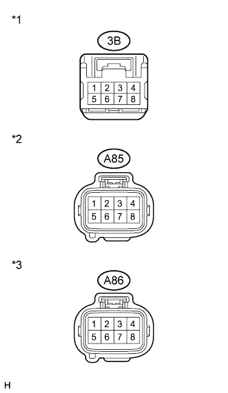
Text in Illustration *1 Front view of wire harness connector
(to Power Distributor (Engine Room Junction Block Assembly))
*2 Front view of wire harness connector
(to Headlight Assembly LH)
*3 Front view of wire harness connector
(to Headlight Assembly RH)
Disconnect the 3B power distributor (engine room junction block assembly) connector.
-
Disconnect the A85 or A86 headlight assembly connector.
-
Measure the resistance according to the value(s) in the table below.
Standard Resistance LH Side (B2430) Tester Connection Condition Specified Condition 3B-4 - A85-4 Always Below 1 Ω 3B-4 - Body ground Always 10 kΩ or higher RH Side (B2431) Tester Connection Condition Specified Condition 3B-3 - A86-4 Always Below 1 Ω 3B-3 - Body ground Always 10 kΩ or higher
NG
REPAIR OR REPLACE HARNESS OR CONNECTOR
OK
REPLACE POWER DISTRIBUTOR (ENGINE ROOM JUNCTION BLOCK ASSEMBLY) Click here
-
-
CHECK HARNESS AND CONNECTOR (MAIN BODY ECU - HEADLIGHT ASSEMBLY)
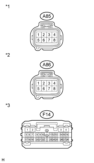
Text in Illustration *1 Front view of wire harness connector
(to Headlight Assembly LH)
*2 Front view of wire harness connector
(to Headlight Assembly RH)
*3 Front view of wire harness connector
(to Main Body ECU (Multiplex Network Body ECU))
-
Disconnect the F14 main body ECU (multiplex network body ECU) connector.
-
Disconnect the A85 or A86 headlight assembly connector.
-
Measure the resistance to the according value(s) in the table below.
Standard Resistance LH Side (B2430) Tester Connection Condition Specified Condition F14-21 (LLEW) - A85-5 Always Below 1 Ω F14-21 (LLEW) - Body ground Always 10 kΩ or higher RH Side (B2431) Tester Connection Condition Specified Condition F14-8 (RLEW) - A86-5 Always Below 1 Ω F14-8 (RLEW) - Body ground Always 10 kΩ or higher
NG
REPAIR OR REPLACE HARNESS OR CONNECTOR
OK
REPLACE MAIN BODY ECU (MULTIPLEX NETWORK BODY ECU) Click here
-