LIGHTING SYSTEM, Diagnostic DTC:B2416

| DTC Code | DTC Name |
|---|---|
| B2416 | Height Control Sensor Malfunction |
DESCRIPTION
w/o Air Suspension System:
The DTC is stored when the AFS ECU (headlight swivel ECU assembly) detects malfunctions in the rear height control sensor sub-assembly RH power source or rear height control sensor sub-assembly RH.
| DTC No. | DTC Detecting Condition | Trouble Area |
|---|---|---|
| B2416 |
|
|
w/ Air Suspension System:
-
The DTC is stored when the AFS ECU (headlight swivel ECU assembly) detects malfunctions in the front height control sensor LH power source or front height control sensor LH.
-
The DTC is stored when the AFS ECU (headlight swivel ECU assembly) detects malfunctions in the rear height control sensor LH power source or rear height control sensor LH.
| DTC No. | DTC Detecting Condition | Trouble Area |
|---|---|---|
| B2416 |
|
|
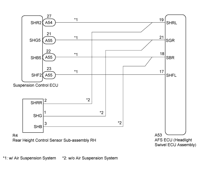
WIRING DIAGRAM
INSPECTION PROCEDURE
PROCEDURE
-
CHECK FOR DTC
-
Clear the DTCs Click here.
-
Check for DTCs Click here.
OK DTC B2416 is not output.
NG 
CHECK VEHICLE CONDITION Click here
OK 
USE SIMULATION METHOD TO CHECK Click here
-
-
CHECK VEHICLE CONDITION
-
Check the vehicle condition.
Result Result Proceed to w/o Air Suspension System A w/ Air Suspension System B
B
CHECK FOR DTC (AIR SUSPENSION SYSTEM) Click here
A 
-
-
READ VALUE USING INTELLIGENT TESTER
-
Connect the intelligent tester to the DLC3.
-
Turn the power switch on (IG).
-
Turn the intelligent tester on.
-
Enter the following menus: Body / AFS / Data List.
-
Read the display on the intelligent tester.
AFS Tester Display Measurement Item/Range Normal Condition Diagnostic Note Height Sens Pw Supply Val Rear height control sensor power supply value / 0 to 6.25 V Approx. 5.0 V - OK Normal conditions listed above are displayed.
NG
CHECK HARNESS AND CONNECTOR (AFS ECU - REAR HEIGHT CONTROL SENSOR SUB-ASSEMBLY RH) Click here
OK
-
-
INSPECT REAR HEIGHT CONTROL SENSOR SUB-ASSEMBLY RH
-
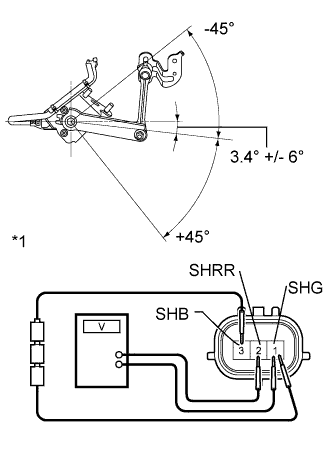
Text in Illustration *1 Component without harness connected
(Rear Height Control Sensor Sub-assembly RH)
Connect 3 dry cell batteries (1.5 V) in series.
-
Remove the rear height control sensor sub-assembly RH Click here.
-
Connect a positive (+) lead from the battery to terminal 3 (SHB) and a negative (-) lead from the battery to terminal 1 (SHG).
-
Measure the voltage between terminals 2 (SHRR) and 1 (SHG) while slowly moving the link up and down.
Standard Voltage Tester Connection Condition Specified Condition 2 (SHRR) - 1 (SHG) +45° (High) 4.05 V 0° (Normal) 2.25 V -45° (Low) 0.45 V
NG 
REPLACE REAR HEIGHT CONTROL SENSOR SUB-ASSEMBLY RH Click here
OK
REPLACE AFS ECU (HEADLIGHT SWIVEL ECU ASSEMBLY) Click here
-
-
CHECK HARNESS AND CONNECTOR (AFS ECU - REAR HEIGHT CONTROL SENSOR SUB-ASSEMBLY RH)
-
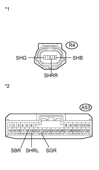
Text in Illustration *1 Front view of wire harness connector
(to Rear Height Control Sensor Sub-assembly RH)
*2 Front view of wire harness connector
(to AFS ECU (Headlight Swivel ECU Assembly))
Disconnect the A53 AFS ECU (headlight swivel ECU assembly) connector.
-
Disconnect the R4 rear height control sensor sub-assembly RH connector.
-
Measure the resistance according to the value(s) in the table below.
Standard Resistance Tester Connection Condition Specified Condition A53-18 (SBR) - R4-3 (SHB) Always Below 1 Ω A53-19 (SHRL) - R4-2 (SHRR) Always Below 1 Ω A53-21 (SGR) - R4-1 (SHG) Always Below 1 Ω A53-18 (SBR) - Body ground Always 10 kΩ or higher A53-19 (SHRL) - Body ground Always 10 kΩ or higher A53-21 (SGR) - Body ground Always 10 kΩ or higher
NG
REPAIR OR REPLACE HARNESS OR CONNECTOR
OK
-
-
INSPECT REAR HEIGHT CONTROL SENSOR SUB-ASSEMBLY RH
-
Text in Illustration *1 Component without harness connected
(Rear Height Control Sensor Sub-assembly RH)
Connect 3 dry cell batteries (1.5 V) in series.
-
Remove the rear height control sensor sub-assembly RH Click here.
-
Connect a positive (+) lead from the battery to terminal 3 (SHB) and a negative (-) lead from the battery to terminal 1 (SHG).
-
Measure the voltage between terminals 2 (SHRR) and 1 (SHG) while slowly moving the link up and down.
Standard Voltage Tester Connection Condition Specified Condition 2 (SHRR) - 1 (SHG) +45° (High) 4.05 V 0° (Normal) 2.25 V -45° (Low) 0.45 V
NG
REPLACE REAR HEIGHT CONTROL SENSOR SUB-ASSEMBLY RH Click here
OK
REPLACE AFS ECU (HEADLIGHT SWIVEL ECU ASSEMBLY) Click here
-
-
CHECK FOR DTC (AIR SUSPENSION SYSTEM)
-
Check for DTCs Click here.
OK DTC "C1712 Front Height Control Sensor LH Circuit Malfunction" and "C1714 Rear Height Control Sensor LH Circuit Malfunction" are not output.
NG
GO TO AIR SUSPENSION SYSTEM Click here
OK
-
-
READ VALUE USING INTELLIGENT TESTER
-
Connect the intelligent tester to the DLC3.
-
Turn the power switch on (IG).
-
Turn the intelligent tester on.
-
Enter the following menus: Body / AFS / Data List.
-
Read the display on the intelligent tester.
AFS Tester Display Measurement Item/Range Normal Condition Diagnostic Note Height Sens Pw Supply Val Rear height control sensor power supply value / 0 to 6.25 V Approx. 5.0 V - OK Normal conditions listed above are displayed.
NG
CHECK HARNESS AND CONNECTOR (SUSPENSION CONTROL ECU - AFS ECU) Click here
OK
-
-
REPLACE SUSPENSION CONTROL ECU
-
Temporarily replace the suspension control ECU with a new or normally functioning one Click here for LHD, Click here for RHD).
-
Check for DTCs Click here.
OK DTC B2416 is not output.
NG
REPLACE AFS ECU (HEADLIGHT SWIVEL ECU ASSEMBLY) Click here
OK
END
-
-
CHECK HARNESS AND CONNECTOR (SUSPENSION CONTROL ECU - AFS ECU)
-
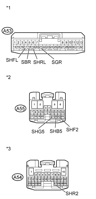
Text in Illustration *1 Front view of wire harness connector
(to AFS ECU (Headlight Swivel ECU Assembly))
*2 Front view of wire harness connector
(to Suspension Control ECU)
*3 Front view of wire harness connector
(to Suspension Control ECU)
Disconnect the A53 AFS ECU (headlight swivel ECU assembly) connector.
-
Disconnect the A54 and A55 suspension control ECU connectors.
-
Measure the resistance according to the value(s) in the table below.
Standard Resistance Tester Connection Condition Specified Condition A53-17 (SHFL) - A55-23 (SHF2) Always Below 1 Ω A53-18 (SBR) - A55-22 (SHB5) Always Below 1 Ω A53-19 (SHRL) - A54-27 (SHR2) Always Below 1 Ω A53-21 (SGR) - A55-21 (SHG5) Always Below 1 Ω A53-17 (SHFL) - Body ground Always 10 kΩ or higher A53-18 (SBR) - Body ground Always 10 kΩ or higher A53-19 (SHRL) - Body ground Always 10 kΩ or higher A53-21 (SGR) - Body ground Always 10 kΩ or higher
NG
REPAIR OR REPLACE HARNESS OR CONNECTOR
OK
-
-
REPLACE SUSPENSION CONTROL ECU
-
Temporarily replace the suspension control ECU with a new or normally functioning one Click here for LHD, Click here for RHD).
-
Check for DTCs Click here.
OK DTC B2416 is not output.
NG
REPLACE AFS ECU (HEADLIGHT SWIVEL ECU ASSEMBLY) Click here
OK
END
-