LIGHTING SYSTEM, Diagnostic DTC:B1244

| DTC Code | DTC Name |
|---|---|
| B1244 | Light Sensor Circuit Malfunction |
DESCRIPTION
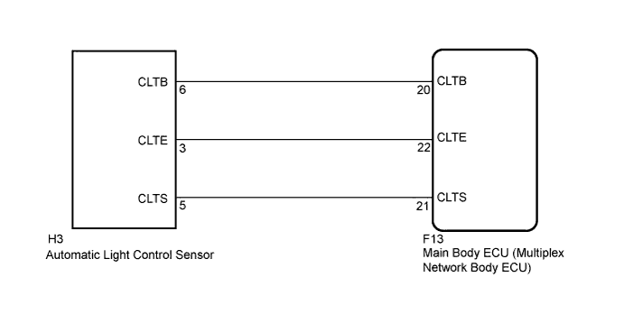
The automatic light control sensor detects ambient light, converts it into an electrical signal, and outputs it to the main body ECU (multiplex network body ECU). The main body ECU (multiplex network body ECU) turns on or off the headlights and taillights according to the signal.
| DTC No. | DTC Detecting Condition | Trouble Area |
|---|---|---|
| B1244 |
|
|
WIRING DIAGRAM
INSPECTION PROCEDURE
PROCEDURE
-
READ VALUE USING INTELLIGENT TESTER
-
Connect the intelligent tester to the DLC3.
-
Turn the power switch on (IG).
-
Turn the intelligent tester on.
-
Enter the following menu items: Body / Main Body / Data List.
-
Read the display on the intelligent tester.
Main Body Tester Display Measurement Item/Range Normal Condition Diagnostic Note Illumination Rate Illumination rate information/0 ms to 99.99 ms Value is output according to ambient light levels - OK Normal condition listed above is displayed.
NG 
CHECK HARNESS AND CONNECTOR (MAIN BODY ECU - AUTOMATIC LIGHT CONTROL SENSOR) Click here
OK 
REPLACE MAIN BODY ECU (MULTIPLEX NETWORK BODY ECU) Click here
-
-
CHECK HARNESS AND CONNECTOR (MAIN BODY ECU - AUTOMATIC LIGHT CONTROL SENSOR)
-
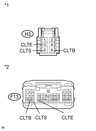
Text in Illustration *1 Front view of wire harness connector
(to Automatic Light Control Sensor)
*2 Front view of wire harness connector
(to Main Body ECU (Multiplex Network Body ECU))
Disconnect the H3 automatic light control sensor connector.
-
Disconnect the F13 main body ECU (multiplex network body ECU) connector.
-
Measure the resistance according to the value(s) in the table below.
Standard Resistance Tester Connection Condition Specified Condition F13-22 (CLTE) - H3-3 (CLTE) Always Below 1 Ω F13-21 (CLTS) - H3-5 (CLTS) Always Below 1 Ω F13-20 (CLTB) - H3-6 (CLTB) Always Below 1 Ω F13-22 (CLTE) - Body ground Always 10 kΩ or higher F13-21 (CLTS) - Body ground Always 10 kΩ or higher F13-20 (CLTB) - Body ground Always 10 kΩ or higher
NG 
REPAIR OR REPLACE HARNESS OR CONNECTOR
OK 
-
-
INSPECT MAIN BODY ECU (MULTIPLEX NETWORK BODY ECU)
-
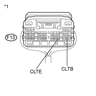
Text in Illustration *1 Component with harness connected
(Main Body ECU (Multiplex Network Body ECU))
Reconnect the F13 main body ECU (multiplex network body ECU) connector.
-
Measure the voltage and resistance according to the value(s) in the table below.
Standard Voltage Tester Connection Condition Specified Condition F13-20 (CLTB) - F13-22 (CLTE) Power switch off Below 1 V Power switch on (IG) 11 to 14 V Standard Resistance Tester Connection Condition Specified Condition F13-22 (CLTE) - Body ground Always Below 1 Ω
NG
REPLACE MAIN BODY ECU (MULTIPLEX NETWORK BODY ECU) Click here
OK
-
-
INSPECT AUTOMATIC LIGHT CONTROL SENSOR
-
Reconnect the H3 automatic light control sensor connector.
-
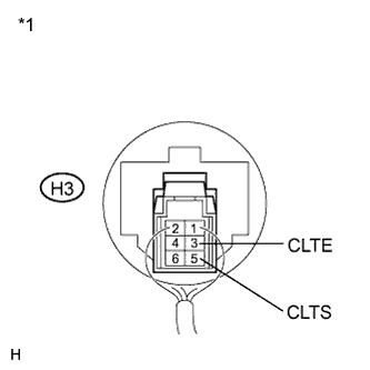
Connect an oscilloscope to the automatic light control sensor connector.
Text in Illustration *1 Component with harness connected
(Automatic Light Control Sensor)
-
Check the waveform.
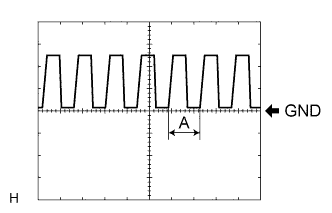
OK Tester Connection Tool Setting Condition Specified Condition H3-3 (CLTE) - H3-5 (CLTS) 5 V/DIV., 5 ms./DIV. Power switch on (IG), light control switch in AUTO position Correct waveform is as shown Tech Tips
If the ambient light becomes brighter, width A becomes narrower.
NG
REPLACE AUTOMATIC LIGHT CONTROL SENSOR Click here
OK
REPLACE MAIN BODY ECU (MULTIPLEX NETWORK BODY ECU) Click here
-