LIGHTING SYSTEM Door Mirror Foot Light Circuit
DESCRIPTION
The outer mirror control ECU receives the signal from the main body ECU (multiplex network body ECU) to control the door mirror foot light.
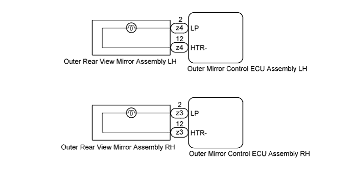
WIRING DIAGRAM
INSPECTION PROCEDURE
PROCEDURE
-
PERFORM ACTIVE TEST USING INTELLIGENT TESTER
-
Connect the intelligent tester to the DLC3.
-
Turn the power switch on (IG).
-
Turn the intelligent tester on.
-
Enter the following menus: Body / Mirror L or Mirror R / Active Test.
-
Check that the door mirror foot lights operate.
Mirror L Tester Display Test Part Control Range Diagnostic Note Foot Light Door mirror foot light LH ON/OFF - Mirror R Tester Display Test Part Control Range Diagnostic Note Foot Light Door mirror foot light RH ON/OFF - Result Result Proceed to OK A NG (Door mirror foot light LH does not comes on) B NG (Door mirror foot light RH does not comes on) C
B 
INSPECT OUTER REAR VIEW MIRROR ASSEMBLY LH Click here
C
INSPECT OUTER REAR VIEW MIRROR ASSEMBLY RH Click here
A 
PROCEED TO NEXT SUSPECTED AREA SHOWN IN PROBLEM SYMPTOMS TABLE Click here
-
-
INSPECT OUTER REAR VIEW MIRROR ASSEMBLY LH
-
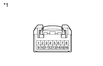
Text in Illustration *1 Component without harness connected
(Outer Rear View Mirror Assembly LH)
Remove the outer rear view mirror assembly LH Click here.
-
Connect a positive (+) lead from the battery to terminal 2 and a negative (-) lead to terminal 12.
-
Check that the outer mirror foot light comes on.
OK Door mirror foot light comes on.
NG 
REPLACE OUTER REAR VIEW MIRROR ASSEMBLY LH Click here
OK
REPLACE OUTER MIRROR CONTROL ECU ASSEMBLY (LH) Click here
-
-
INSPECT OUTER REAR VIEW MIRROR ASSEMBLY RH
-
Text in Illustration *1 Component without harness connected
(Outer Rear View Mirror Assembly RH)
Remove the outer rear view mirror assembly RH Click here.
-
Connect a positive (+) lead from the battery to terminal 2 and a negative (-) lead to terminal 12.
-
Check that the outer mirror foot light comes on.
OK Door mirror foot light comes on.
NG
REPLACE OUTER REAR VIEW MIRROR ASSEMBLY RH Click here
OK
REPLACE OUTER MIRROR CONTROL ECU ASSEMBLY (RH) Click here
-