LIGHTING SYSTEM Back-up Light Circuit
DESCRIPTION
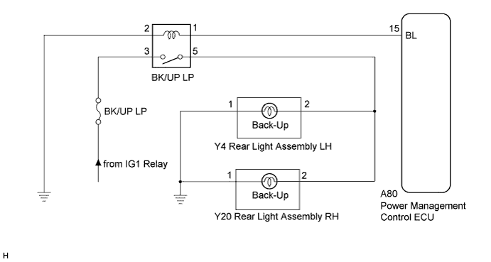
The power management control ECU receives shift position R signal and controls the back up light relay.
WIRING DIAGRAM
INSPECTION PROCEDURE
Note
Inspect the fuses for circuits related to this system before performing the following inspection procedure.
PROCEDURE
-
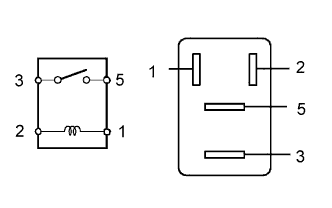
INSPECT BACK UP LIGHT RELAY (BK/UP LP)
-
Remove the back up light relay from the No. 2 engine room relay block.
-
Measure the resistance according to the value(s) in the table below.
Standard resistance Tester Connection Condition Specified Condition 3 - 5 Voltage is not applied between terminals 1 and 2 10 kΩ or higher 3 - 5 Voltage is applied between terminals 1 and 2 Below 1 Ω
NG 
REPLACE BACK UP LIGHT RELAY
OK 
-
-
CHECK HARNESS AND CONNECTOR (RELAY - POWER MANAGEMENT CONTROL ECU AND BODY GROUND)
-
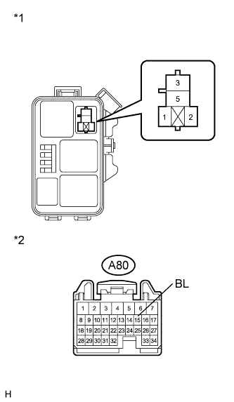
Text in Illustration *1 No. 2 Engine Room Relay Block *2 Front view of wire harness connector
(to Power Management Control ECU)
Disconnect the A80 power management control ECU connector.
-
Remove the back up light relay from the No. 2 engine room relay block.
-
Measure the resistance according to the value(s) in the table below.
Standard Resistance Tester Connection Condition Specified Condition A80-15 (BL) - Relay terminal 1 Always Below 1 Ω A80-15 (BL) - Body ground Always 10 kΩ or higher Relay terminal 2 - Body ground Always Below 1 Ω
NG
REPAIR OR REPLACE HARNESS OR CONNECTOR
OK
-
-
INSPECT POWER MANAGEMENT CONTROL ECU
-
Reconnect the A80 power management control ECU connector.
-
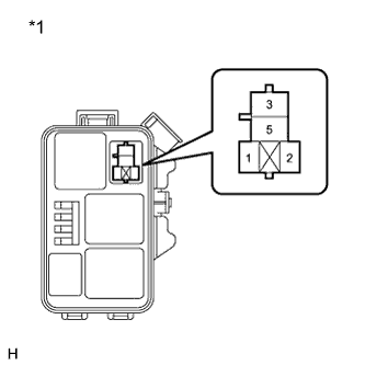
Text in Illustration *1 No. 2 Engine Room Relay Block Measure the voltage according to the value(s) in the table below.
Standard Voltage Tester connection Condition Specified Condition Relay terminal 1 - Body ground Shift lever in R 11 to 14 V Relay terminal 1 - Body ground Shift lever not in R Below 1 V
NG
PROCEED TO NEXT SUSPECTED AREA SHOWN IN PROBLEM SYMPTOMS TABLE Click here
OK
-
-
CHECK HARNESS AND CONNECTOR (BATTERY - RELAY)
-
Text in Illustration *1 No. 2 Engine Room Relay Block Measure the voltage according to the value(s) in the table below.
Standard Voltage Tester connection Condition Specified Condition Relay terminal 3 - Body ground Power switch on (IG) 11 to 14 V Relay terminal 3 - Body ground Power switch off Below 1 V
NG
REPAIR OR REPLACE HARNESS OR CONNECTOR (BATTERY - RELAY)
OK 
REPAIR OR REPLACE HARNESS OR CONNECTOR (BULB - RELAY AND BODY GROUND)
-