WIPER AND WASHER SYSTEM Wiper ECU Power Source Circuit
DESCRIPTION
This circuit provides power to the windshield wiper switch assembly.
WIRING DIAGRAM
INSPECTION PROCEDURE
PROCEDURE
-
CHECK HARNESS AND CONNECTOR (WINDSHIELD WIPER RELAY ASSEMBLY - BATTERY AND BODY GROUND)
-
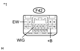
Text in Illustration *1 Front view of wire harness connector
(to Windshield Wiper Switch Assembly)
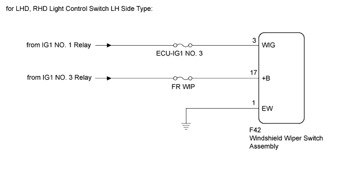
for LHD, RHD Light Control Switch LH Side Type:
-
Disconnect the F42 windshield wiper switch assembly connector.
-
Measure the voltage according to the value(s) in the table below.
Standard Voltage Tester Connection Condition Specified Condition F42-3 (WIG) - Body ground Power switch on (IG) 11 to 14 V F42-17 (+B) - Body ground Power switch on (IG) 11 to 14 V -
Measure the resistance according to the value(s) in the table below.
Standard Resistance Tester Connection Condition Specified Condition F42-1 (EW) - Body ground Always Below 1 Ω
-
-
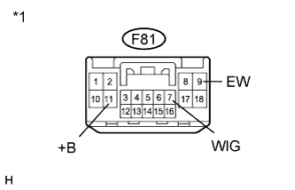
Text in Illustration *1 Front view of wire harness connector
(to Windshield Wiper Switch Assembly)
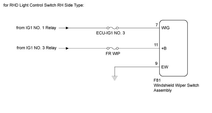
for RHD Light Control Switch RH Side Type:
-
Disconnect the F81 windshield wiper switch assembly connector.
-
Measure the voltage according to the value(s) in the table below.
Standard Voltage Tester Connection Condition Specified Condition F81-7 (WIG) - Body ground Power switch on (IG) 11 to 14 V F81-11 (+B) - Body ground Power switch on (IG) 11 to 14 V -
Measure the resistance according to the value(s) in the table below.
Standard Resistance Tester Connection Condition Specified Condition F81-9 (EW) - Body ground Always Below 1 Ω
-
NG 
REPAIR OR REPLACE HARNESS OR CONNECTOR
OK 
PROCEED TO NEXT SUSPECTED AREA SHOWN IN PROBLEM SYMPTOMS TABLE Click here
-