WIPER AND WASHER SYSTEM Speed Signal Circuit
DESCRIPTION
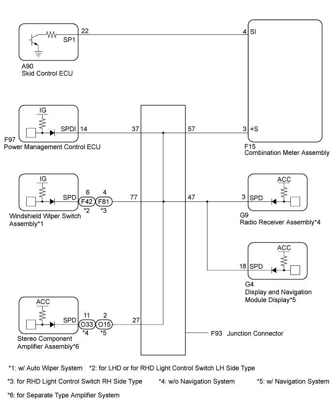
The windshield wiper relay assembly receives a vehicle speed signal from the combination meter to control the automatic windshield wiper system.
A voltage of 12 V or 5 V is output from the combination meter assembly and then input to the skid control ECU.
A voltage of 12 V or 5 V is output from each ECU or relay and then input to the combination meter assembly.
The signal is changed to a pulse signal at the transistor in the combination meter assembly.
Each ECU controls the respective system based on the pulse signal.
If a short occurs in any of the ECUs or in the wire harness connected to an ECU, all systems in the diagram below will not operate normally.
WIRING DIAGRAM
-
for 2GR-FXE
INSPECTION PROCEDURE
PROCEDURE
-
CHECK COMBINATION METER SYSTEM
-
The circuit that sends vehicle speed signals to the combination meter system is inspected in the meter section Click here.
NEXT 
-
-
CHECK HARNESS AND CONNECTOR (WINDSHIELD WIPER SWITCH ASSEMBLY - COMBINATION METER)
-
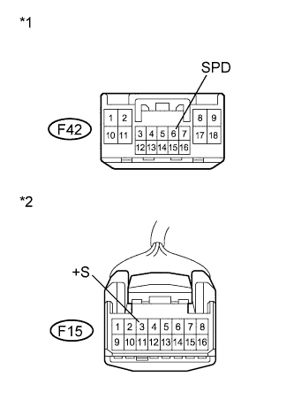
Text in Illustration *1 Front view of wire harness connector
(to Windshield Wiper Switch Assembly)
*2 Front view of wire harness connector
(to Combination Meter Assembly)
for LHD, RHD Light Control Switch LH Side Type:
-
Disconnect the F42 windshield wiper switch assembly connector and F15 combination meter connector.
-
Measure the resistance according to the value(s) in the table below.
Standard Resistance Tester Connection Condition Specified Condition F42-6 (SPD) - F15-3 (+S) Always Below 1 Ω
-
-
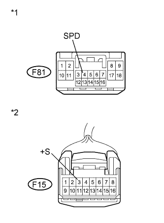
Text in Illustration *1 Front view of wire harness connector
(to Windshield Wiper Switch Assembly)
*2 Front view of wire harness connector
(to Combination Meter Assembly)
for RHD Light Control Switch RH Side Type:
-
Disconnect the F81 windshield wiper switch assembly connector and F15 combination meter connector.
-
Measure the resistance according to the value(s) in the table below.
Standard Resistance Tester Connection Condition Specified Condition F81-4 (SPD) - F15-3 (+S) Always Below 1 Ω
-
NG 
REPAIR OR REPLACE HARNESS OR CONNECTOR
OK
-
-
INSPECT COMBINATION METER (SPEED SENSOR SIGNAL)
-
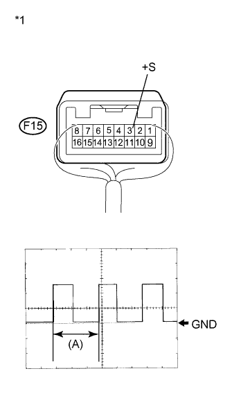
Text in Illustration *1 Component with harness connected
(Combination Meter)
Check the output waveform.
-
Remove the combination meter assembly with the connector still connected.
-
Connect an oscilloscope to terminal F15-3 (+S) and body ground.
-
Turn the power switch on (IG).
-
Turn a wheel slowly.
-
Check the signal waveform according to the condition(s) in the table below.
Item Condition Tool setting 5 V/DIV., 20 ms./DIV. Vehicle condition Driving at approx. 20 km/h (12 mph) OK The waveform is displayed as shown in the illustration. Tech Tips
When the system is functioning normally, one wheel revolution generates 4 pulses. As the vehicle speed increases, the width indicated by (A) shown in the illustration narrows.
-
NG
REPLACE COMBINATION METER Click here
OK 
PROCEED TO NEXT SUSPECTED AREA SHOWN IN PROBLEM SYMPTOMS TABLE Click here
-