WIPER AND WASHER SYSTEM Washer Fluid Level Warning Switch Circuit
DESCRIPTION
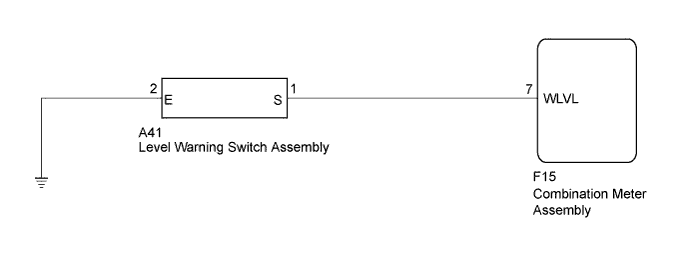
The combination meter receives washer fluid level warning switch condition (on or off) information to control the washer fluid level warning system.
WIRING DIAGRAM
INSPECTION PROCEDURE
PROCEDURE
-
INSPECT LEVEL WARNING SWITCH ASSEMBLY
Tech Tips
The following check should be performed with the windshield washer motor and pump installed to the washer jar.
-
Fill the washer jar with washer fluid.
-
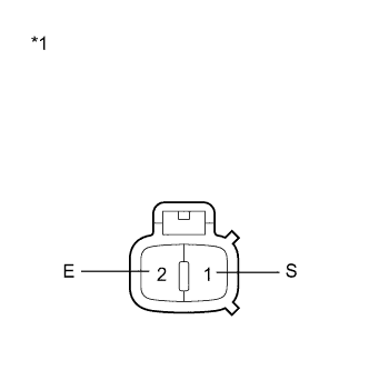
Text in Illustration *1 Component without harness connected
(Level Warning Switch Assembly)
Measure the resistance according to the value(s) in the table below.
Standard Resistance Tester Connection Condition Specified Condition 1 (S) - 2 (E) Fluid volume is more than 800 ml 10 kΩ or higher 1 (S) - 2 (E) Fluid volume is less than 600 ml Below 1 Ω
NG 
REPLACE LEVEL WARNING SWITCH ASSEMBLY Click here
OK 
-
-
CHECK HARNESS AND CONNECTOR (LEVEL WARNING SWITCH - COMBINATION METER AND BODY GROUND)
-
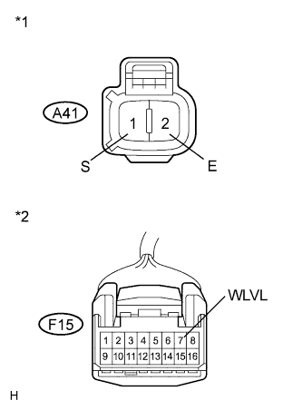
Text in Illustration *1 Front view of wire harness connector
(to Level Warning Switch Assembly)
*2 Front view of wire harness connector
(to Combination Meter Assembly)
Disconnect the F15 combination meter connector.
-
Measure the resistance according to the value(s) in the table below.
Standard Resistance Tester Connection Condition Specified Condition F15-7 (WLVL) - A41-1 (S) Always Below 1 Ω A41-2 (E) - Body ground Always Below 1 Ω F15-7 (WLVL) - Body ground Always 10 kΩ or higher
NG
REPAIR OR REPLACE HARNESS OR CONNECTOR
OK 
PROCEED TO NEXT SUSPECTED AREA SHOWN IN PROBLEM SYMPTOMS TABLE Click here
-