WIPER AND WASHER SYSTEM Headlight Cleaner Motor and Relay Circuit
DESCRIPTION
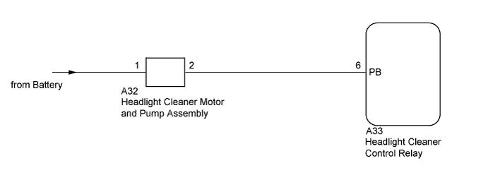
The headlight cleaner control relay controls the headlight cleaner motor and pump assembly.
WIRING DIAGRAM
INSPECTION PROCEDURE
PROCEDURE
-
INSPECT HEADLIGHT CLEANER MOTOR AND PUMP ASSEMBLY
Tech Tips
The following check should be performed with the headlight cleaner motor and pump assembly installed to the washer jar.
-
Fill the washer jar with washer fluid.
-
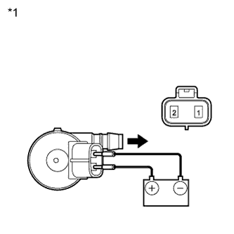
Text in Illustration *1 Component without harness connected
(Headlight Cleaner Motor and Pump Assembly)
Connect a battery positive (+) lead to terminal 1 of the headlight cleaner motor and pump assembly, and a battery negative (-) lead to terminal 2.
-
Check that washer fluid flows from the washer jar.
OK Washer fluid is pumped from the washer jar.
NG 
REPLACE HEADLIGHT CLEANER MOTOR AND PUMP ASSEMBLY Click here
OK 
-
-
CHECK HARNESS AND CONNECTOR (HEADLIGHT CLEANER MOTOR CIRCUIT)
-
Connect the headlight cleaner motor and pump assembly connector.
-
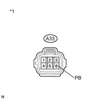
Text in Illustration *1 Front view of wire harness connector
(to Headlight Cleaner Control Relay)
Disconnect the A33 headlight cleaner control relay connector.
-
Measure the voltage according to the value(s) in the table below.
Standard Voltage Tester Connection Condition Specified Condition A33-6 (PB) - Body ground Always 11 to 14 V
NG
REPAIR OR REPLACE HARNESS OR CONNECTOR (HEADLIGHT CLEANER CONTROL RELAY - BATTERY)
OK 
PROCEED TO NEXT SUSPECTED AREA SHOWN IN PROBLEM SYMPTOMS TABLE Click here
-