WIPER AND WASHER SYSTEM Headlight Cleaner Switch Circuit
DESCRIPTION
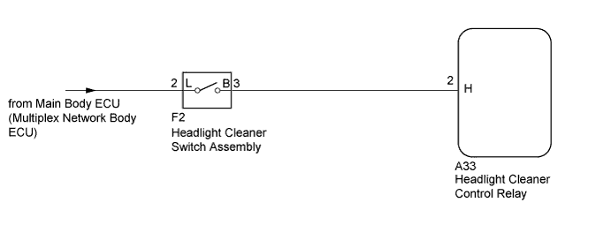
This circuit detects the conditions (on or off) of the headlight cleaner switch assembly.
WIRING DIAGRAM
INSPECTION PROCEDURE
PROCEDURE
-
INSPECT HEADLIGHT CLEANER CONTROL RELAY (H SIGNAL)
-
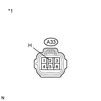
Text in Illustration *1 Front view of wire harness connector
(to Headlight Cleaner Control Relay)
Disconnect the A33 headlight cleaner control relay connector.
-
Measure the voltage according to the value(s) in the table below.
Standard Voltage Tester Connection Switch Condition Specified Condition A33-2 (H) - Body ground Light control switch in head and headlight cleaner switch on 11 to 14 V A33-2 (H) - Body ground Headlight cleaner switch off Below 1 V
NG 
INSPECT HEADLIGHT CLEANER SWITCH ASSEMBLY Click here
OK 
PROCEED TO NEXT SUSPECTED AREA SHOWN IN PROBLEM SYMPTOMS TABLE Click here
-
-
INSPECT HEADLIGHT CLEANER SWITCH ASSEMBLY
-
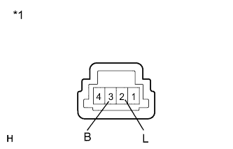
Text in Illustration *1 Component without harness connected
(Headlight Cleaner Switch Assembly)
Remove the headlight cleaner switch assembly Click here.
-
Measure the resistance according to the value(s) in the table below.
Standard Resistance Tester Connection Switch Condition Specified Condition 2 (L) - 3 (B) Headlight cleaner switch off 10 kΩ or higher 2 (L) - 3 (B) Headlight cleaner switch on Below 1 Ω
NG 
REPLACE HEADLIGHT CLEANER SWITCH ASSEMBLY Click here
OK
REPAIR OR REPLACE HARNESS OR CONNECTOR (MAIN BODY ECU - HEADLIGHT CLEANER CONTROL RELAY)
-