WIPER AND WASHER SYSTEM Rain Sensor Circuit
DESCRIPTION
The windshield wiper switch assembly receives a signal from the rain sensor to control the auto wiper system.
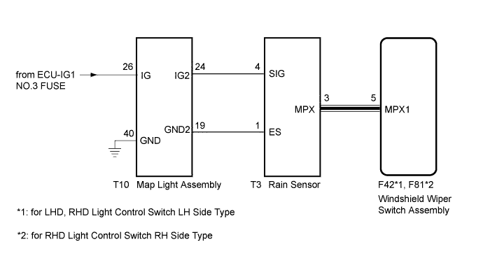
WIRING DIAGRAM
INSPECTION PROCEDURE
PROCEDURE
-
CHECK HARNESS AND CONNECTOR (POWER SOURCE CIRCUIT)
-
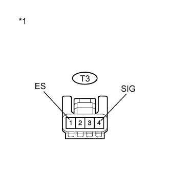
Text in Illustration *1 Front view of wire harness connector
(to Rain Sensor)
Disconnect the T3 rain sensor connector.
-
Measure the voltage according to the value(s) in the table below.
Standard Voltage Tester Connection Condition Specified Condition T3-4 (SIG) - T3-1 (ES) Always 11 to 14 V
NG 
REPAIR OR REPLACE HARNESS OR CONNECTOR
OK 
-
-
CHECK HARNESS AND CONNECTOR (RAIN SENSOR - WINDSHIELD WIPER SWITCH ASSEMBLY)
-
for LHD, RHD Light Control Switch LH Side Type:
-
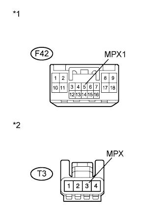
Text in Illustration *1 Front view of wire harness connector
(to Windshield Wiper Switch Assembly)
*2 Front view of wire harness connector
(to Rain Sensor)
Disconnect the F42 windshield wiper switch assembly connector.
-
Disconnect the T3 rain sensor connector.
-
Measure the resistance according to the value(s) in the table below.
Standard Resistance Tester Connection Condition Specified Condition F42-5 (MPX1) - T3-3 (MPX) Always Below 1 Ω T3-3 (MPX) - Body ground Always 10 kΩ or higher
-
-
for RHD Light Control Switch RH Side Type:
-

Text in Illustration *1 Front view of wire harness connector
(to Windshield Wiper Switch Assembly)
*2 Front view of wire harness connector
(to Rain Sensor)
Disconnect the F81 windshield wiper switch assembly connector.
-
Disconnect the T3 rain sensor connector.
-
Measure the resistance according to the value(s) in the table below.
Standard Resistance Tester Connection Condition Specified Condition F81-5 (MPX1) - T3-3 (MPX) Always Below 1 Ω T3-3 (MPX) - Body ground Always 10 kΩ or higher
-
NG
REPAIR OR REPLACE HARNESS OR CONNECTOR
OK
-
-
INSPECT RAIN SENSOR
-
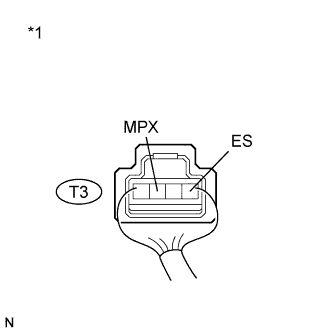
Text in Illustration *1 Component without harness connected
(Rain Sensor)
Reconnect the rain sensor connector.
-
Connect an oscilloscope to the automatic light control sensor connector.
-
Check for pulses.
OK Tester Connection Condition Specified Condition T3-3 (MPX) - T3-1 (ES) Power switch on (IG) Pulse generation
NG
REPLACE RAIN SENSOR Click here
OK 
PROCEED TO NEXT SUSPECTED AREA SHOWN IN PROBLEM SYMPTOMS TABLE Click here
-