WIPER AND WASHER SYSTEM Front Wiper Motor Circuit
DESCRIPTION
The windshield wiper switch assembly controls the windshield wiper motor assembly.
WIRING DIAGRAM
INSPECTION PROCEDURE
PROCEDURE
-
INSPECT WINDSHIELD WIPER MOTOR ASSEMBLY
-
for LHD:
-
Remove the windshield wiper motor assembly Click here.
-
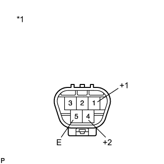
Text in Illustration *1 Component without harness connected
(Windshield Wiper Motor Assembly)
Check LO operation.
Connect a battery positive (+) lead to terminal 1 (+1) and a negative (-) lead to terminal 5 (E), and check that the motor operates at low speed (LO).
OK Motor operates at low speed (LO). -
Check HI operation.
Connect a battery positive (+) lead to terminal 4 (+2) and a negative (-) lead to terminal 5 (E), and check that the motor operates at high speed (HI).
OK Motor operates at high speed (HI).
-
-
for RHD:
-
Remove the windshield wiper motor assembly Click here.
-
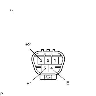
Text in Illustration *1 Component without harness connected
(Windshield Wiper Motor Assembly)
Check LO operation.
Connect a battery positive (+) lead to terminal 5 (+1) and a negative (-) lead to terminal 4 (E), and check that the motor operates at low speed (LO).
OK Motor operates at low speed (LO). -
Check HI operation.
Connect a battery positive (+) lead to terminal 3 (+2) and a negative (-) lead to terminal 4 (E), and check that the motor operates at high speed (HI).
OK Motor operates at high speed (HI).
-
NG 
REPLACE WINDSHIELD WIPER MOTOR ASSEMBLY Click here
OK 
-
-
CHECK HARNESS AND CONNECTOR (WINDSHIELD WIPER MOTOR ASSEMBLY - BATTERY AND BODY GROUND)
-
for LHD:
-
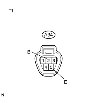
Text in Illustration *1 Front view of wire harness connector
(to Windshield Wiper Motor Assembly)
Disconnect the A34 windshield wiper motor connector.
-
Measure the voltage according to the value(s) in the table below.
Standard Voltage Tester Connection Condition Specified Condition A34-2 (B) - Body ground Power switch on (IG) 11 to 14 V -
Measure the resistance according to the value(s) in the table below.
Standard Resistance Tester Connection Condition Specified Condition A34-5 (E) - Body ground Always Below 1 Ω
-
-
for RHD:
-
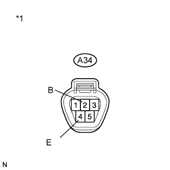
Text in Illustration *1 Front view of wire harness connector
(to Windshield Wiper Motor Assembly)
Disconnect the A34 windshield wiper motor connector.
-
Measure the voltage according to the value(s) in the table below.
Standard Voltage Tester Connection Condition Specified Condition A34-2 (B) - Body ground Power switch on (IG) 11 to 14 V -
Measure the resistance according to the value(s) in the table below.
Standard Resistance Tester Connection Condition Specified Condition A34-4 (E) - Body ground Always Below 1 Ω
-
NG
REPAIR OR REPLACE HARNESS OR CONNECTOR
OK
-
-
CHECK HARNESS AND CONNECTOR (WINDSHIELD WIPER MOTOR - WINDSHIELD WIPER SWITCH)
-
for LHD:
-
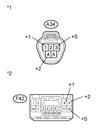
Text in Illustration *1 Front view of wire harness connector
(to Windshield Wiper Motor Assembly)
*2 Front view of wire harness connector
(to Windshield Wiper Switch Assembly)
Disconnect the F42 windshield wiper switch assembly connector.
-
Measure the resistance according to the value(s) in the table below.
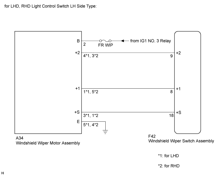
Standard Resistance Tester Connection Condition Specified Condition F42-8 (+1) - A34-1 (+1) Always Below 1 Ω A34-1 (+1) - Body ground Always 10 kΩ or higher F42-9 (+2) - A34-4 (+2) Always Below 1 Ω A34-4 (+2) - Body ground Always 10 kΩ or higher F42-18 (+S) - A34-3 (+S) Always Below 1 Ω A34-3 (+S) - Body ground Always 10 kΩ or higher
-
-
for RHD Light Control Switch LH Side Type:
-
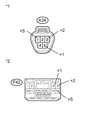
Text in Illustration *1 Front view of wire harness connector
(to Windshield Wiper Motor Assembly)
*2 Front view of wire harness connector
(to Windshield Wiper Switch Assembly)
Disconnect the F42 windshield wiper switch assembly connector.
-
Measure the resistance according to the value(s) in the table below.
Standard Resistance Tester Connection Condition Specified Condition F42-8 (+1) - A34-5 (+1) Always Below 1 Ω A34-5 (+1) - Body ground Always 10 kΩ or higher F42-9 (+2) - A34-3 (+2) Always Below 1 Ω A34-3 (+2) - Body ground Always 10 kΩ or higher F42-18 (+S) - A34-1 (+S) Always Below 1 Ω A34-1 (+S) - Body ground Always 10 kΩ or higher
-
-
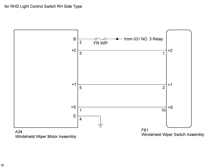
for RHD Light Control Switch RH Side Type:
-
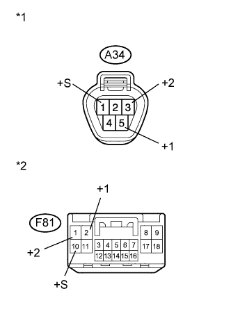
Text in Illustration *1 Front view of wire harness connector
(to Windshield Wiper Motor Assembly)
*2 Front view of wire harness connector
(to Windshield Wiper Switch Assembly)
Disconnect the F81 windshield wiper switch assembly connector.
-
Measure the resistance according to the value(s) in the table below.
Standard Resistance Tester Connection Condition Specified Condition F81-2 (+1) - A34-5 (+1) Always Below 1 Ω A34-5 (+1) - Body ground Always 10 kΩ or higher F81-1 (+2) - A34-3 (+2) Always Below 1 Ω A34-3 (+2) - Body ground Always 10 kΩ or higher F81-10 (+S) - A34-1 (+S) Always Below 1 Ω A34-1 (+S) - Body ground Always 10 kΩ or higher
-
NG
REPAIR OR REPLACE HARNESS OR CONNECTOR
OK 
PROCEED TO NEXT SUSPECTED AREA SHOWN IN PROBLEM SYMPTOMS TABLE Click here
-