OUTER REAR VIEW MIRROR DISASSEMBLY

-
REMOVE OUTER REAR VIEW MIRROR GLASS
-
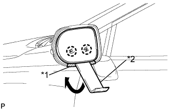
Push the upper part of the mirror surface and tilt it.
-
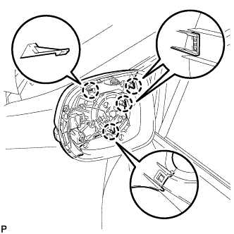
Apply protective tape to the areas shown in the illustration.
-
Using a moulding remover, disengage the 2 claws at the lower part of the outer rear view mirror.
Text in Illustration *1 Protective Tape *2 Moulding Remover -
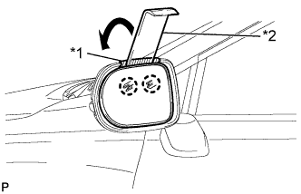
Push the lower part of the mirror surface and tilt it.
-
Apply protective tape to the areas shown in the illustration.
-
Using a moulding remover, disengage the 2 claws at the upper part of the outer rear view mirror, and separate the outer rear view mirror glass.
Text in Illustration *1 Protective Tape *2 Moulding Remover -
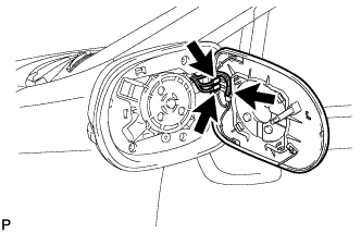
Disconnect each connector and remove the outer rear view mirror glass.
-
-
REMOVE SIDE TURN SIGNAL LIGHT ASSEMBLY
-
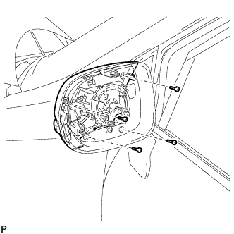
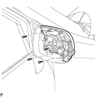
Remove the 4 screws.
-
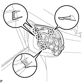
Disengage the 4 claws and disconnect the outer mirror cover with the side turn signal light assembly.
-
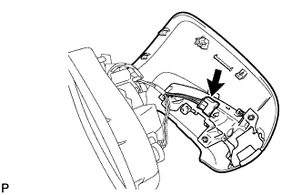
Disconnect the connector and remove the outer mirror cover with the side turn signal light assembly.
-
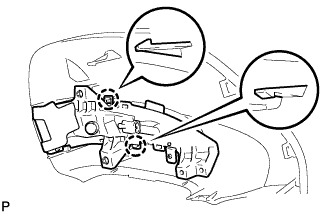
Disengage the 2 claws and remove the side turn signal light assembly with the turn signal trim from the outer mirror cover.
-
Disengage the 3 claws and remove the side turn signal light assembly from the turn signal trim.
-
-
REMOVE SIDE TELEVISION CAMERA ASSEMBLY (w/ Side Monitor System)
-
Remove the 4 screws.
-
Disengage the 4 claws and disconnect the outer mirror cover with the side turn signal light assembly.
-
Disconnect the connector and remove the outer mirror cover with the side turn signal light assembly.
-
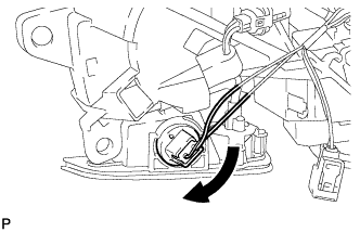
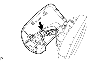
Disconnect the foot light bulb with the bulb socket as shown in the illustration.
-
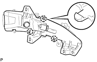
Insert a 0.9 mm (0.0354 in.) spark plug gap gauge or similar tool to the side of the claw engagement portion as shown in the illustration, tilt up the claw on the connector and disconnect the camera connector.
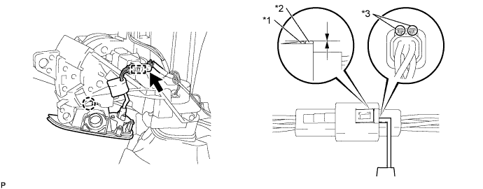
Text in Illustration *1 Claw *2 Protrusion *3 Insert Position - - Note
-
Insert the gauge enough so that the claw becomes the same height as the protrusion of the connector housing. If the gauge is inserted too far, or if the notch on the claw is lifted directly using a screwdriver, the claw may be damaged.
-
When the claw on the connector is damaged, replace the luggage door opening switch assembly.
-
-
Disengage the connector clamp.
-
Disengage the claw and remove the foot light unit.
-
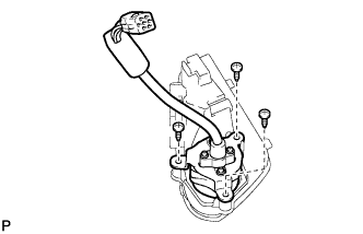
Remove the 3 screws and side television camera assembly.
-