WIPER AND WASHER SYSTEM TERMINALS OF ECU

-
CHECK WINDSHIELD WIPER SWITCH ASSEMBLY (for LHD, RHD Light Control Switch LH Side Type)

-
Disconnect the F42 windshield wiper switch assembly connector.
-
Measure the voltage and resistance according to the value(s) in the table below.
Terminal No. (Symbol) Wiring Color Terminal Description Condition Specified Condition F42-1 (EW) - Body ground W-B - Body ground Body ground Always Below 1 Ω F42-3 (WIG) - Body ground R - Body ground Power source circuit Power switch on (IG) 11 to 14 V Power switch off Below 1 V F42-17 (+B) - Body ground L - Body ground Power source circuit Power switch on (IG) 11 to 14 V Power switch off Below 1 V If the result is not as specified, there may be a malfunction in the wire harness.
-
Reconnect the F42 windshield wiper switch assembly connector.
-
Measure the voltage according to the value(s) in the table below.
Terminal No. (Symbol) Wiring Color Terminal Description Condition Specified Condition F42-2 (WF) - Body ground B - Body ground Front washer motor circuit Front washer switch on Below 1 V Front washer switch off 11 to 14 V F42-5 (MPX1) - Body ground V - Body ground Rain sensor signal Power switch on (IG) Pulse generation F42-6 (SPD) - Body ground GR - Body ground Speed signal Driving at approx. 20 km/h (12 mph) Pulse generation F42-7 (TAIL)*1 - Body ground L - Body ground Light control switch tail position signal circuit Light control switch in tail position 11 to 14 V Light control switch off Below 1 V F42-8 (+1) - Body ground SB - Body ground Front wiper motor LO speed signal circuit Front wiper motor in LO operation 11 to 14 V Front wiper motor off Below 1 V F42-9 (+2) - Body ground GR - Body ground Front wiper motor HI speed signal circuit Front wiper motor in HI operation 11 to 14 V Front wiper motor off Below 1 V F42-18 (+S) - Body ground R - Body ground Front wiper motor operation signal Front wiper motor operates 11 to 14 V Front wiper motor off Below 1 V If the result is not as specified, the windshield wiper switch assembly may have a malfunction.
-
-
CHECK WINDSHIELD WIPER SWITCH ASSEMBLY (for RHD Light Control Switch RH Side Type)

-
Disconnect the F81 windshield wiper switch assembly connector.
-
Measure the voltage and resistance according to the value(s) in the table below.
Terminal No. (Symbol) Wiring Color Terminal Description Condition Specified Condition F81-7 (WIG) - Body ground R - Body ground Power source circuit Power switch on (IG) 11 to 14 V Power switch off Below 1 V F81-9 (EW) - Body ground W-B - Body ground Body ground Always Below 1 Ω F81-11 (+B) - Body ground L - Body ground Power source circuit Power switch on (IG) 11 to 14 V Power switch off Below 1 V If the result is not as specified, there may be a malfunction in the wire harness.
-
Reconnect the F81 windshield wiper switch assembly connector.
-
Measure the voltage according to the value(s) in the table below.
Terminal No. (Symbol) Wiring Color Terminal Description Condition Specified Condition F81-1 (+2) - Body ground GR - Body ground Front wiper motor HI speed signal circuit Front wiper motor in HI operation 11 to 14 V Front wiper motor off Below 1 V F81-2 (+1) - Body ground SB - Body ground Front wiper motor LO speed signal circuit Front wiper motor in LO operation 11 to 14 V Front wiper motor off Below 1 V F81-3 (TAIL) - Body ground L - Body ground Light control switch tail position signal circuit Light control switch in tail position 11 to 14 V Light control switch off Below 1 V F81-4 (SPD) - Body ground GR - Body ground Speed signal Driving at approx. 20 km/h (12 mph) Pulse generation F81-5 (MPX1) - Body ground V - Body ground Rain sensor signal Power switch on (IG) Pulse generation F81-8 (WF) - Body ground B - Body ground Front washer motor circuit Front washer switch on Below 1 V Front washer switch off 11 to 14 V F81-10 (+S) - Body ground R - Body ground Front wiper motor operation signal Front wiper motor operates 11 to 14 V Front wiper motor off Below 1 V If the result is not as specified, the windshield wiper switch assembly may have a malfunction.
-
-
CHECK MAP LIGHT ASSEMBLY (w/ Auto Wiper System)

-
Disconnect the T10 map light assembly connector.
-
Measure the voltage and resistance according to the value(s) in the table below.
Terminal No. (Symbol) Wiring Color Terminal Description Condition Specified Condition T10-26 (IG) - Body ground P - Body ground Power source circuit Power switch on (IG) 11 to 14 V Power switch off Below 1 V T10-40 (GND) - Body ground W - Body ground Body ground Always Below 1 Ω If the result is not as specified, there may be a malfunction in the wire harness.
-
Reconnect the T10 map light assembly connector.
-
Measure the voltage according to the value(s) in the table below.
Terminal No. (Symbol) Wiring Color Terminal Description Condition Specified Condition T10-24 (IG2) - T10-19 (GND2) G - W-B Power source circuit Power switch on (IG) 11 to 14 V Power switch off Below 1 V If the result is not as specified, the map light assembly may have a malfunction.
-
-
CHECK HEADLIGHT CLEANER CONTROL RELAY
-
Disconnect the A33 headlight cleaner control relay connector.
-
Measure the voltage and resistance according to the value(s) in the table below.
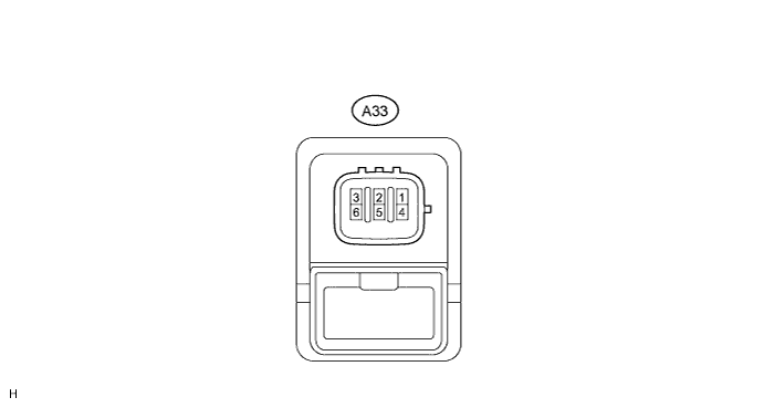
Terminal No. (Symbol) Wiring Color Terminal Description Condition Specified Condition A33-2 (H) - A33-4 (E) W - W-B Headlight cleaner switch operation signal Headlight cleaner switch off 11 to 14 V Headlight cleaner switch on Below 1 V A33-3 (IG) - A33-4 (E) BR - W-B Power switch on (IG) signal (Power source circuit) Power switch off Below 1 V Power switch on (IG) 11 to 14 V A33-4 (E) - Body ground W-B - Body ground Body ground Always Below 1 Ω A33-5 (FRWA) - A33-4 (E) P - W-B Front washer switch signal Front washer switch off 11 to 14 V Front washer switch on Below 1 V If the result is not as specified, there may be a malfunction in the wire harness.
-
-
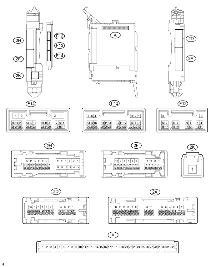
CHECK INSTRUMENT PANEL JUNCTION BLOCK ASSEMBLY AND MAIN BODY ECU (MULTIPLEX NETWORK BODY ECU)
-
Measure the voltage according to the value(s) in the table below.
Terminal No. (Symbol) Wiring Color Terminal Description Condition Specified Condition F14-20 (HDLO) - Body ground L - Body ground Low beam headlight signal Power switch on (IG), light control switch in head position Below 1 V Power switch on (IG), light control switch off 4.2 V or higher
-