POWER MIRROR CONTROL SYSTEM Driver Side Power Mirror cannot be Adjusted with Power Mirror Switch
SYSTEM DESCRIPTION
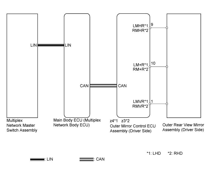
When the mirror adjust switch is operated, the multiplex network master switch assembly detects the switch operation and sends the mirror adjust switch signal to the main body ECU (multiplex network body ECU) via LIN communication. The main body ECU (multiplex network body ECU) then sends the mirror adjust switch signal to the outer mirror control ECU (driver side) via CAN communication. On receiving the signal, the outer mirror control ECU (driver side) operates the vertical and horizontal mirror motors, which are built into the outer rear view mirror assembly (driver side), to adjust the mirror surface position.
WIRING DIAGRAM
INSPECTION PROCEDURE
PROCEDURE
-
CHECK CAN COMMUNICATION SYSTEM
-
Check for CAN communication system DTCs Click here.
OK CAN communication DTC is not output.
NG 
GO TO CAN COMMUNICATION SYSTEM (DIAGNOSTIC TROUBLE CODE CHART) Click here
OK 
-
-
READ VALUE USING INTELLIGENT TESTER (OUTER MIRROR SWITCH ASSEMBLY)
-
Connect the intelligent tester to the DLC3.
-
Turn the power switch on (IG).
-
Turn the intelligent tester on.
-
Enter the following menus: Body / Master Switch / Data List.
-
for LHD
-
Read the Data List according to the display on the intelligent tester.
Master Switch Tester Display Measurement Item/Range Normal Condition Diagnostic Note Mirror Selection SW (L) Mirror select switch signal for LH mirror / ON or OFF ON: Switch in L position
OFF: Switch off or in R position
- Mirror Position SW (R) Mirror adjust switch signal (right) / ON or OFF ON: Mirror adjust switch pressed right
OFF: Mirror adjust switch not pressed right
Check with the mirror select switch in the L position. Mirror Position SW (L) Mirror adjust switch signal (left) / ON or OFF ON: Mirror adjust switch pressed left
OFF: Mirror adjust switch not pressed left
Check with the mirror select switch in the L position. Mirror Position SW (Up) Mirror adjust switch signal (up) / ON or OFF ON: Mirror adjust switch pressed up
OFF: Mirror adjust switch not pressed up
Check with the mirror select switch in the L position. Mirror Position SW (Dwn) Mirror adjust switch signal (down) / ON or OFF ON: Mirror adjust switch pressed down
OFF: Mirror adjust switch not pressed down
Check with the mirror select switch in the L position.
-
-
for RHD
-
Read the Data List according to the display on the intelligent tester.
Master Switch Tester Display Measurement Item/Range Normal Condition Diagnostic Note Mirror Selection SW (R) Mirror select switch signal for RH mirror / ON or OFF ON: Switch in R position
OFF: Switch off or in L position
- Mirror Position SW (R) Mirror adjust switch signal (right) / ON or OFF ON: Mirror adjust switch pressed right
OFF: Mirror adjust switch not pressed right
Check with the mirror select switch in the R position. Mirror Position SW (L) Mirror adjust switch signal (left) / ON or OFF ON: Mirror adjust switch pressed left
OFF: Mirror adjust switch not pressed left
Check with the mirror select switch in the R position. Mirror Position SW (Up) Mirror adjust switch signal (up) / ON or OFF ON: Mirror adjust switch pressed up
OFF: Mirror adjust switch not pressed up
Check with the mirror select switch in the R position. Mirror Position SW (Dwn) Mirror adjust switch signal (down) / ON or OFF ON: Mirror adjust switch pressed down
OFF: Mirror adjust switch not pressed down
Check with the mirror select switch in the R position. OK On the intelligent tester screen, ON or OFF is displayed for each item according to the table above.
-
NG
REPLACE MULTIPLEX NETWORK MASTER SWITCH ASSEMBLY Click here
OK
-
-
PERFORM ACTIVE TEST USING INTELLIGENT TESTER (POWER MIRROR CONTROL FUNCTION)
-
for LHD: Enter the following menus: Body / Mirror L / Active Test.
-
for RHD: Enter the following menus: Body / Mirror R / Active Test.
-
Perform the Active Test according to the display on the intelligent tester.
Mirror L / Mirror R Tester Display Test Part Control Range Diagnostic Note Mirror Up/Down Mirror vertical operation Up / Down - Mirror Right/Left Mirror horizontal operation Right / Left - OK Power mirror operation is normal.
NG 
INSPECT OUTER REAR VIEW MIRROR ASSEMBLY (DRIVER SIDE) Click here
OK 
REPLACE OUTER MIRROR CONTROL ECU ASSEMBLY (DRIVER SIDE) Click here
-
-
INSPECT OUTER REAR VIEW MIRROR ASSEMBLY (DRIVER SIDE)
-
for LHD:
-
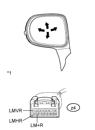
Text in Illustration *1 Component without harness connected
(Outer Rear View Mirror Assembly LH)
Remove the outer rear view mirror assembly LH Click here.
-
Apply auxiliary battery voltage and check the operation of the outer rear view mirror assembly LH.
OK Measurement Condition Specified Condition Auxiliary battery positive (+) → Terminal z4-1 (LMVR)
Auxiliary battery negative (-) → Terminal z4-10 (LM+R)
Turns upward Auxiliary battery negative (-) → Terminal z4-1 (LMVR)
Auxiliary battery positive (+) → Terminal z4-10 (LM+R)
Turns downward Auxiliary battery positive (+) → Terminal z4-9 (LMHR)
Auxiliary battery negative (-) → Terminal z4-10 (LM+R)
Turns left Auxiliary battery negative (-) → Terminal z4-9 (LMHR)
Auxiliary battery positive (+) → Terminal z4-10 (LM+R)
Turns right
-
-
for RHD:
-
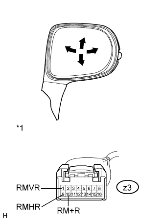
Text in Illustration *1 Component without harness connected
(Outer Rear View Mirror Assembly RH)
Remove the outer rear view mirror assembly RH Click here.
-
Apply auxiliary battery voltage and check the operation of the outer rear view mirror assembly RH.
OK Measurement Condition Specified Condition Auxiliary battery positive (+) → Terminal z3-1 (RMVR)
Auxiliary battery negative (-) → Terminal z3-10 (RM+R)
Turns upward Auxiliary battery negative (-) → Terminal z3-1 (RMVR)
Auxiliary battery positive (+) → Terminal z3-10 (RM+R)
Turns downward Auxiliary battery positive (+) → Terminal z3-9 (RMHR)
Auxiliary battery negative (-) → Terminal z3-10 (RM+R)
Turns left Auxiliary battery negative (-) → Terminal z3-9 (RMHR)
Auxiliary battery positive (+) → Terminal z3-10 (RM+R)
Turns right
-
NG
REPLACE OUTER REAR VIEW MIRROR ASSEMBLY (DRIVER SIDE) Click here
OK
REPLACE OUTER MIRROR CONTROL ECU ASSEMBLY (DRIVER SIDE) Click here
-