BACK DOOR REASSEMBLY

-
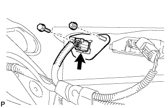
INSTALL RADIO SETTING CONDENSER
-
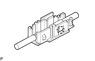
Engage the claw to install a new terminal cover to wire harness.
-
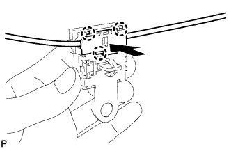
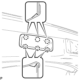
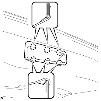
Engage the 3 claws to install the new terminal cover with wire harness to a new condenser.
-
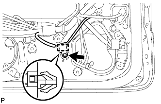
Engage the clamp to temporarily install the new radio setting condenser with wire harness to the back door.
-
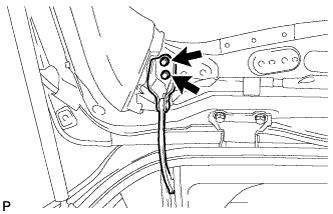
Install the new radio setting condenser with the bolt.
- Torque:
- 8.4 N*m { 86 kgf*cm, 74 in.*lbf }
-
-
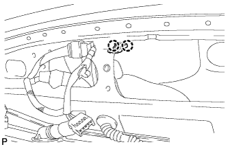
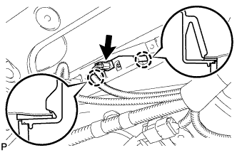
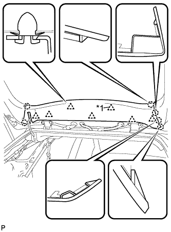
INSTALL NO. 3 ANTENNA CORD SUB-ASSEMBLY
-
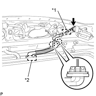
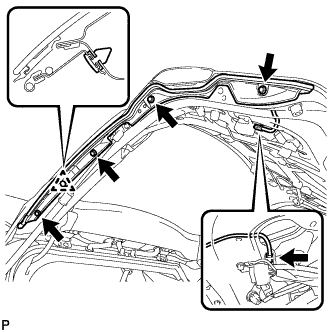
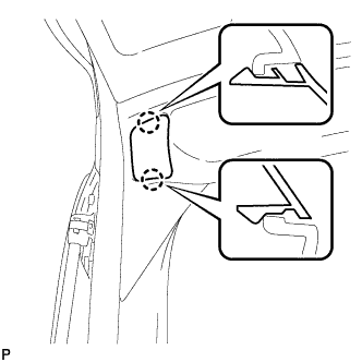
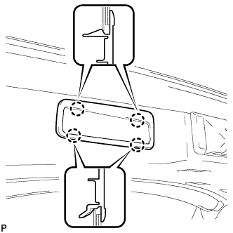
Text in Illustration *1 Clamp *2 Grommet Engage the 2 claws to install the antenna cord grommet of back door side.
-
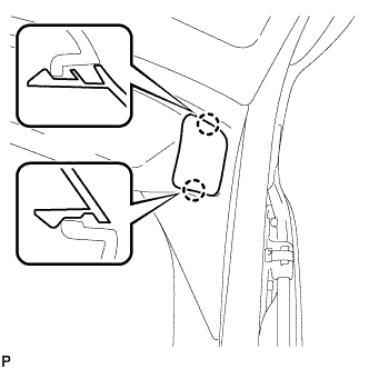
Install the antenna cord grommet of vehicle body side.
-
Engage the clamp.
-
Connect the connector.
-
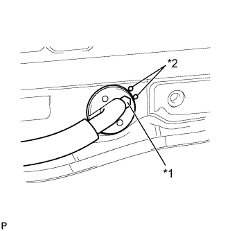
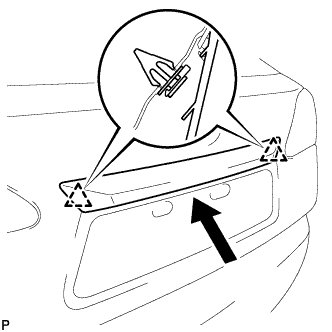
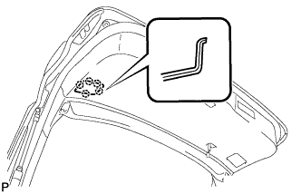
Text in Illustration *1 Grommet Side Match Mark *2 Vehicle Body Side Match Mark Set the position of the antenna cord grommet of back door side as shown in the illustration.
-
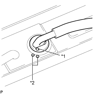
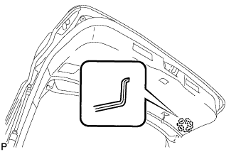
Text in Illustration *1 Grommet Side Match Mark *2 Vehicle Body Side Match Mark Set the position of the antenna cord grommet of vehicle body side as shown in the illustration.
-
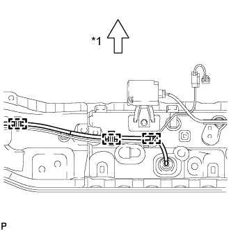
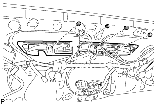
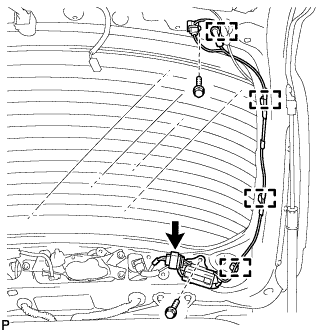
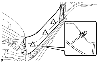
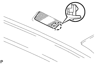
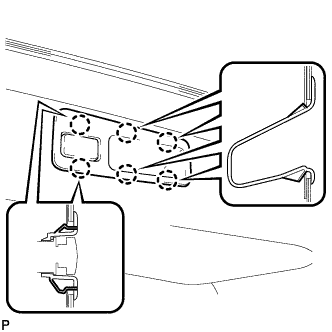
Text in Illustration *1 Front Engage the 3 clamps.
-
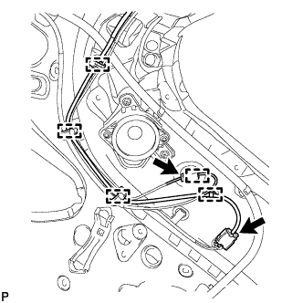
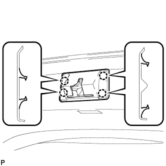
Engage the 5 clamps and install the No. 3 antenna cord sub-assembly.
-
Connect the 2 connectors.
-
-
INSTALL ROOF HEADLINING ASSEMBLY
Tech Tips
Refer to the procedure from Install Roof Headlining Assembly Click here.
-
INSTALL REAR WASHER NOZZLE
-
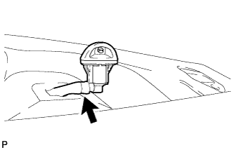
Connect the washer hose.
-
Engage the 2 claws to install the rear washer nozzle.
-
-
INSPECT REAR WASHER NOZZLE
-
With the engine running, check that the center stream of washer fluid sprays on the windshield within the hatched area shown in the illustration.
Standard Washer fluid hits the windshield in the area shown in the illustration. 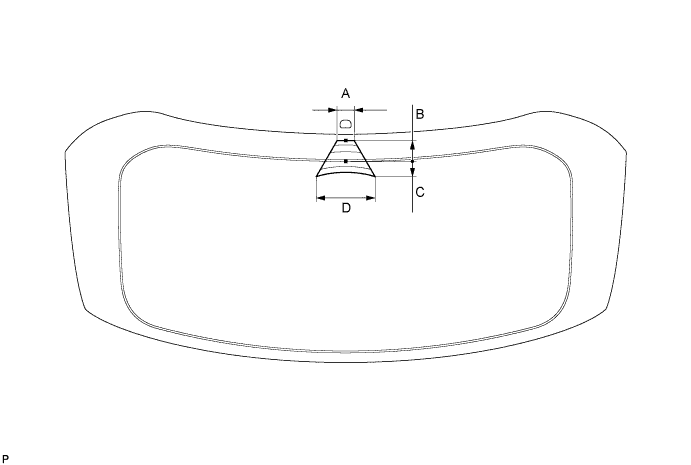
Standard Clearance Area Measurement A 43 mm (1.693 in.) B 50 mm (1.969 in.) C 40 mm (1.575 in.) D 150 mm (5.906 in.) Tech Tips
If the result is not as specified, replace the malfunctioning rear washer nozzle.
-
-
ADJUST REAR WASHER NOZZLE
-
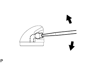
Using a screwdriver, adjust the direction of the rear washer nozzle.
Note
Do not use a safety pin or other pointed tools. Doing so may damage the inside of the washer nozzle.
Tech Tips
Use a thin-bladed screwdriver with an approximately 1 mm (0.0394 in.) thick tip.
-
-
INSTALL REAR WIPER MOTOR AND BRACKET ASSEMBLY
-
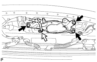
Install the rear wiper motor and bracket assembly with the 3 bolts.
- Torque:
- 5.5 N*m { 56 kgf*cm, 49 in.*lbf }
-
Connect the connector.
-
Engage the clamp.
-
-
INSTALL REAR WIPER MOTOR GROMMET
-
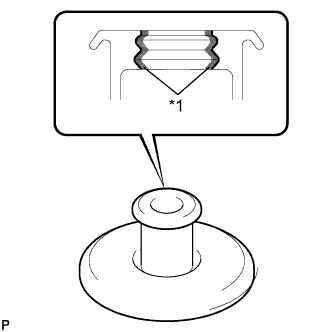
Text in Illustration *1 MP grease Apply MP grease to the entire surface of the rear wiper motor grommet lip.
Tech Tips
Make sure that the hole does not get clogged with grease and the grooves on the lip are filled with grease.
-
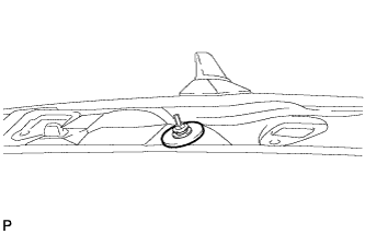
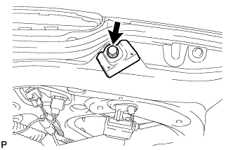
Install the rear wiper motor grommet.
-
-
INSTALL REAR WIPER ARM AND BLADE ASSEMBLY
-
Operate the wiper and stop the windshield wiper motor at the automatic stop position.
-
When reusing the rear wiper arm and blade assembly:
-
Text in Illustration *1 Wiper Arm Serration Clean the wiper arm serrations.
-
-
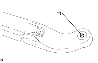
When reusing the rear wiper motor assembly:
-
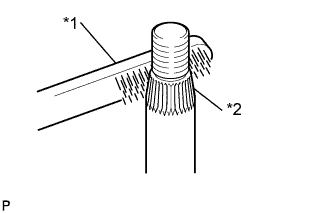
Text in Illustration *1 Wire Brush *2 Wiper Pivot Serration Clean the wiper pivot serrations with a wire brush.
-
-
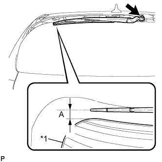
Text in Illustration *1 Ceramic Line Install the rear wiper arm and blade assembly with the nut to the position shown in the illustration.
- Torque:
- 5.5 N*m { 56 kgf*cm, 49 in.*lbf }
Standard Clearance Area Measurement A 30 mm (1.181 in.) Tech Tips
Hold the wiper arm by hand while tightening the nut.
-
Operate the rear wiper while spraying washer fluid onto the back door glass. Make sure that the rear wiper functions properly and the wiper does not come into contact with the vehicle body.
-
-
INSTALL REAR SPOILER SUB-ASSEMBLY
-
Install the 2 pins.
-
Install a new clip.
-
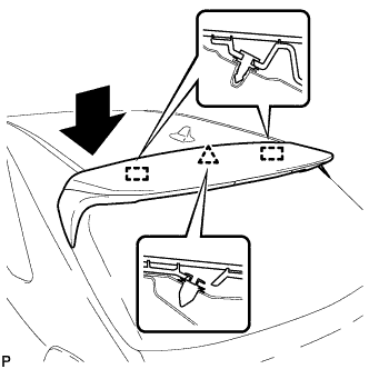
Engage the clip and 2 pins to install the rear spoiler sub-assembly.
-
Install the 5 nuts.
- Torque:
- 5.9 N*m { 60 kgf*cm, 52 in.*lbf }
-
Install the 2 hole plugs.
-
Connect each connector.
-
-
INSTALL REAR TELEVISION CAMERA ASSEMBLY (w/ Rear Monitor)
-
Install the rear television camera assembly with the bolt and nut.
- Torque:
- 10 N*m { 102 kgf*cm, 7 ft.*lbf }
-
Connect the connector.
-
-
INSTALL LICENSE PLATE LIGHT ASSEMBLY LH
-
Engage the 2 claws to install the license plate light assembly.
-
Connect the connector.
-
-
INSTALL LICENSE PLATE LIGHT ASSEMBLY RH
Tech Tips
Use the same procedure for the RH side and LH side.
-
INSTALL BACK DOOR OUTSIDE GARNISH SUB-ASSEMBLY
-
Install 2 bolts.
-
Install 2 stud bolts.
-
Install 2 new clips and 4 new gaskets on the back door outside garnish assembly.
-
Engage the 2 clips and install the back door outside garnish sub-assembly.
-
Install the 4 nuts.
- Torque:
- 4.9 N*m { 50 kgf*cm, 43 in.*lbf }
-
Connect each connector.
-
-
INSTALL REAR LIGHT ASSEMBLY LH
-
Install the rear light assembly with the 4 nuts.
- Torque:
- 5.4 N*m { 55 kgf*cm, 48 in.*lbf }
-
Connect each connector.
-
-
INSTALL REAR LIGHT ASSEMBLY RH
Tech Tips
Use the same procedure for the RH side and LH side.
-
INSTALL AMPLIFIER ANTENNA ASSEMBLY
-
Engage the 4 clamps.
-
Install the amplifier antenna assembly with the 2 bolts.
- Torque:
- 8.0 N*m { 82 kgf*cm, 71 in.*lbf }
-
Connect the connector.
-
-
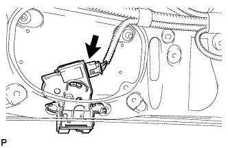
INSTALL POWER BACK DOOR WARNING BUZZER (w/ Power Back Door)
-
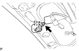
Engage the clamp to install the power back door warning buzzer.
-
Connect the connector.
-
-
INSTALL BACK DOOR LOWER STAY BRACKET LH
-
Clean the threaded portion on the vehicle body with a non-residue solvent.
-
Apply adhesive to the threads of the 2 bolts.
Adhesive Toyota Genuine Adhesive 1324, Three Bond 1324 or equivalent -
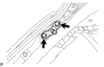
Install the back door lower damper stay bracket with the 2 bolts.
- Torque:
- 8.0 N*m { 82 kgf*cm, 71 in.*lbf }
-
-
INSTALL BACK DOOR LOWER STAY BRACKET RH
Tech Tips
Use the same procedure for the RH side and LH side.
-
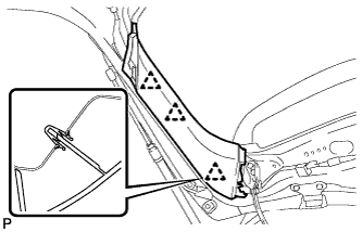
CONNECT BACK DOOR STAY ASSEMBLY LH
-

Install the stop ring to the power back door rod.
-
Install the back door stay assembly LH.
Note
-
Install the back door stay assembly while supporting the back door by hand.
-
Check that the back door stay assembly is engaged in the ball joint and that the back door stay assembly cannot be pulled out.
-
-
-
CONNECT BACK DOOR STAY ASSEMBLY RH
Tech Tips
Use the same procedure for the RH side and LH side.
-
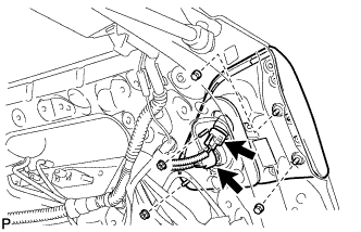
CONNECT POWER BACK DOOR UNIT ASSEMBLY (w/ Power Back Door)
-
Clean the threaded portion on the vehicle body with a non-residue solvent.
-
Apply adhesive to the threads of the 2 bolts.
Adhesive Toyota Genuine Adhesive 1324, Three Bond 1324 or equivalent -
Connect the power back door unit assembly with the 2 bolts.
- Torque:
- 31 N*m { 316 kgf*cm, 23 ft.*lbf }
-
-
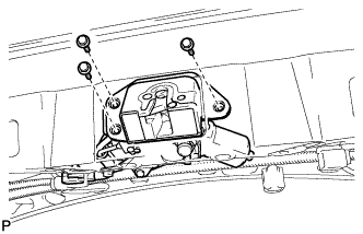
INSTALL POWER BACK DOOR TOUCH SENSOR ASSEMBLY LH (w/ Power Back Door)
-
Engage the clip.
-
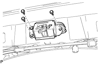
Install the power back door touch sensor assembly with the 4 screws.
- Torque:
- 3.5 N*m { 36 kgf*cm, 31 in.*lbf }
-
Connect the connector.
-
-
INSTALL POWER BACK DOOR TOUCH SENSOR ASSEMBLY RH (w/ Power Back Door)
Tech Tips
Use the same procedure for the RH side and LH side.
-
INSTALL LOWER BACK DOOR STOPPER LH
-
Install the lower back door stopper LH with the bolt.
-
-
INSTALL LOWER BACK DOOR STOPPER RH
Tech Tips
Use the same procedure for the RH side and LH side.
-
INSTALL BACK DOOR LOCK ASSEMBLY (w/o Power Back Door)
-
Apply MP grease to the sliding parts of the back door lock assembly.
-
Install the back door lock assembly with the 3 bolts.
- Torque:
- 13 N*m { 127 kgf*cm, 9 ft.*lbf }
-
Connect the connector.
-
-
INSTALL BACK DOOR LOCK ASSEMBLY (w/ Power Back Door)
-
Apply MP grease to the sliding parts of the back door lock assembly.
-
Install the back door lock assembly with the 3 bolts.
- Torque:
- 13 N*m { 127 kgf*cm, 9 ft.*lbf }
-
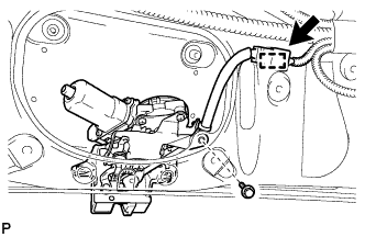
Install the bolt.
- Torque:
- 13 N*m { 127 kgf*cm, 9 ft.*lbf }
-
Engage the clamp.
-
Connect the connector.
-
-
INSTALL BACK DOOR TRIM COVER LH
-
Engage the 3 clips to install the back door trim cover LH.
-
-
INSTALL BACK DOOR TRIM COVER RH
-
Engage the 3 clips to install the back door trim cover RH.
-
-
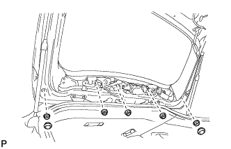
INSTALL BACK DOOR TRIM PANEL ASSEMBLY
-
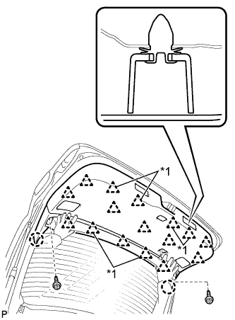
Text in Illustration *1 2-piece Type Clip Engage the 2 claws and 16 clips to install the back door trim panel assembly.
-
Install the 2 screws.
-
-
INSTALL BACK DOOR SERVICE HOLE COVER LH
-
Engage the 5 claws to install the back door service hole cover LH.
-
-
INSTALL BACK DOOR SERVICE HOLE COVER RH
-
Engage the 5 claws to install the back door service hole cover RH.
-
-
INSTALL BACK DOOR UPPER TRIM COVER LH
-
Engage the 2 claws to install the back door upper trim cover LH.
-
-
INSTALL BACK DOOR UPPER TRIM COVER RH
-
Engage the 2 claws to install the back door upper trim cover RH.
-
-
INSTALL NO. 2 ROOM LIGHT ASSEMBLY
-
Connect the connector.
-
Engage the claw to install the No. 2 room light assembly.
-
-
INSTALL BACK DOOR LOCK COVER
-
Engage the 4 claws to install the back door lock cover.
-
-
INSTALL BACK DOOR FINISH COVER LH (w/o Power Back Door)
-
Engage the 6 claws to install the back door finish cover LH.
-
-
INSTALL BACK DOOR TRIM BASE (w/ Power Back Door)
-
Engage the 4 claws to install the back door trim base.
-
-
INSTALL BACK DOOR FINISH COVER RH (w/o Power Back Door)
-
Engage the 6 claws to install the back door finish cover RH.
-
-
INSTALL DOOR PULL HANDLE WITH SWITCH (w/ Power Back Door)
-
Connect the connector.
-
Engage the 6 claws to install the door pull handle with switch.
-
-
INSTALL TONNEAU COVER SUB-ASSEMBLY
-
INSTALL UPPER BACK WINDOW PANEL TRIM
-
Text in Illustration *1 2-piece Type Clip Engage the 7 clips and 6 claws to install the upper back window panel trim.
-
-
ADJUST REAR TELEVISION CAMERA OPTICAL AXIS (CAMERA POSITION SETTINGS) (w/ Parking Assist Monitor System)