REAR SEAT OUTER BELT ASSEMBLY REMOVAL

-
PRECAUTION (w/ Navigation System for HDD)
Note
After the power switch is turned off, the display and navigation module display (HDD navigation system) records various types of memory and settings. As a result, after turning the power switch off, make sure to wait for the time specified in the following table before disconnecting the cable from the negative (-) battery terminal.
Waiting Time after Disconnecting Cable from Negative (-) Battery Terminal Specification Waiting Time w/o Telematics transceiver 60 sec. w/ Telematics transceiver 120 sec. -
REMOVE REAR DECK FLOOR BOX
-

Remove the 3 clips and the rear deck floor box.
-
-
DISCONNECT CABLE FROM NEGATIVE BATTERY TERMINAL
Note
When disconnecting the cable, some systems need to be initialized after the cable is reconnected Click here.
-
REMOVE TONNEAU COVER ASSEMBLY
-
Remove the tonneau cover assembly.
-
-
REMOVE DECK BOARD SUB-ASSEMBLY
-
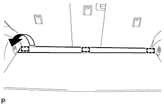
Disengage the 3 fasteners as shown in the illustration.
-
for Compact Spare Tire:
-
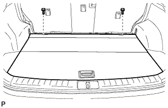
Remove the 2 bolts and remove the deck board sub-assembly.
-
-
for Full Size Spare Tire:
-
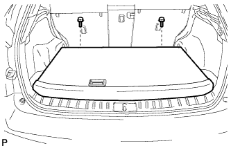
Remove the 2 bolts and remove the deck board sub-assembly.
-
-
-
REMOVE NO. 4 REAR FLOOR BOARD (for LH Side)
-
for Compact Spare Tire:
-
Remove the No. 4 rear floor board Click here.
-
-
-
REMOVE NO. 4 REAR FLOOR BOARD (for LH Side)
-
for Full Size Spare Tire:
-
Remove the No. 4 rear floor board Click here
-
-
-
REMOVE DECK SIDE TRIM BOX LH (for LH Side)
-
for Compact Spare Tire:
-
Remove the deck side trim box LH Click here.
-
-
-
REMOVE DECK SIDE TRIM BOX LH (for LH Side)
-
for Full Size Spare Tire:
-
Remove the deck side trim box LH Click here.
-
-
-
REMOVE FRONT DECK FLOOR BOX (for LH Side)
-
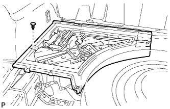
Remove the clip and the front deck floor box.
-
-
REMOVE SPARE WHEEL COVER ASSEMBLY (for RH Side)
-
for Compact Spare Tire:
-
Remove the spare wheel cover assembly Click here.
-
-
-
REMOVE NO. 3 REAR FLOOR BOARD (for RH Side)
-
for Compact Spare Tire:
-
Remove the No. 3 rear floor board Click here.
-
-
-
REMOVE NO. 3 REAR FLOOR BOARD (for RH Side)
-
for Full Size Spare Tire:
-
Remove the No. 3 rear floor board Click here.
-
-
-
REMOVE DECK SIDE TRIM BOX RH (for RH Side)
-
for Compact Spare Tire:
-
Remove the deck side trim box RH Click here.
-
-
-
REMOVE DECK SIDE TRIM BOX RH (for RH Side)
-
for Full Size Spare Tire:
-
Remove the deck side trim box RH Click here.
-
-
-
REMOVE REAR SEAT ASSEMBLY LH (for LH Side)
-
Remove the rear seat assembly LH Click here.
-
-
REMOVE REAR SEAT ASSEMBLY RH (for RH Side)
-
Remove the rear seat assembly RH Click here.
-
-
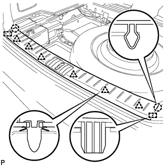
REMOVE REAR DOOR SCUFF PLATE
-
Disengage the 6 claws, 3 clips and guide, and remove the rear door scuff plate LH.
-
-
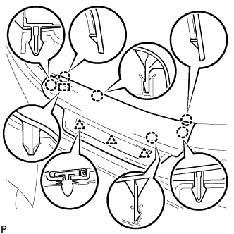
REMOVE REAR FLOOR FINISH PLATE
-
Disengage the 2 claws, 6 clips and 2 guides, and remove the rear floor finish plate.
-
-
REMOVE REAR FLOOR FINISH SIDE PLATE
-
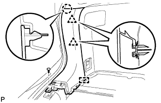
Remove the clip.
-
Disengage the claw and 2 clips.
-
Disengage the guide and remove the rear floor finish side plate LH.
-
-
REMOVE REAR SEAT SIDE COVER
-
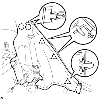
Remove the 2 clips.
-
Disengage the 2 claws and 3 clips, and remove the rear seat side cover LH.
Tech Tips
A part of the clip remains on the vehicle side.
-
-
REMOVE NO. 1 LUGGAGE COMPARTMENT TRIM HOOK (for LH Side)
-
Remove the No. 1 luggage compartment trim hook as shown in the illustration.
-
-
REMOVE NO. 1 LUGGAGE COMPARTMENT TRIM HOOK (for RH Side)
-
Remove the No. 1 luggage compartment trim hook as shown in the illustration.
-
-
REMOVE ROPE HOOK ASSEMBLY
Tech Tips
Use the same procedure for the RH side and the LH side.
-
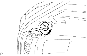
REMOVE RECLINING REMOTE CONTROL BEZEL
-
Using moulding remover A, disengage the 2 bottom claws of the reclining remote control bezel LH.
-
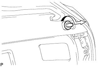
Lift the reclining remote control bezel LH as shown by the arrow (1) in the illustration.
-
Turn the reclining remote control bezel LH as shown by the arrow (2) in the illustration, then disengage the 2 upper claws and remove the bezel.
-
-
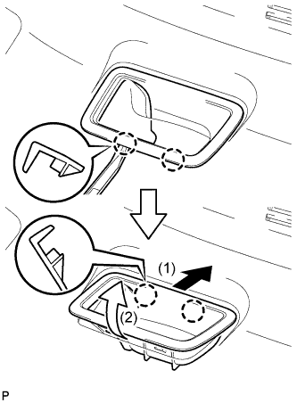
REMOVE HEIGHT CONTROL SWITCH (for RH Side)
-
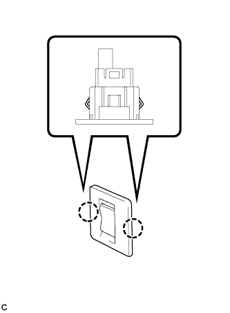
Disengage the 2 claws to remove the height control switch from the deck trim side panel assembly RH.
-
Disconnect the connector.
-
-
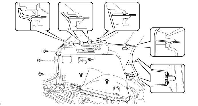
REMOVE DECK TRIM SIDE PANEL ASSEMBLY LH (for LH Side)
-
Remove the 2 screws.
-
Remove the 4 clips.
-
Disengage the 5 claws and 2 clips.
-
Disconnect each connector and remove the deck trim side panel assembly LH.
-
-
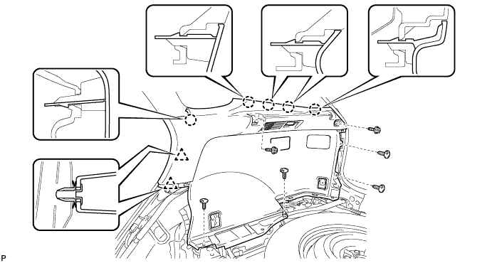
REMOVE DECK TRIM SIDE PANEL ASSEMBLY RH (for RH Side)
-
Remove the 2 screws.
-
Remove the 5 clips.
-
Disengage the 5 claws and 2 clips.
-
Disconnect the connector and remove the deck trim side panel assembly RH.
-
-
DISCONNECT REAR SEAT OUTER BELT ASSEMBLY
-
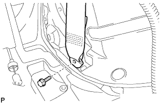
Remove the bolt and disconnect the floor end of the rear seat outer belt assembly.
-
-
REMOVE ROOF SIDE INNER GARNISH ASSEMBLY
-
Disengage the 8 clips.
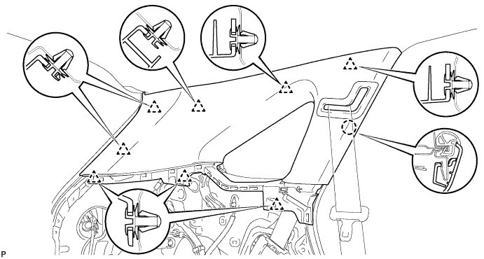
Tech Tips
A part of the clip remains on the vehicle side.
-
Pass the floor anchor of the rear seat outer seat belt assembly LH through the roof side inner garnish assembly LH and remove the roof side inner garnish assembly LH.
-
-
REMOVE REAR SEAT OUTER BELT ASSEMBLY
-
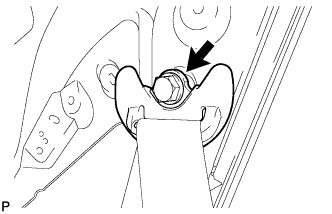
Remove the bolt and disconnect the shoulder anchor of the rear seat outer belt assembly.
Tech Tips
When the bolt is removed, the shoulder anchor of the rear seat outer belt assembly is also removed.
-
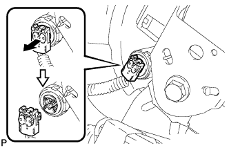
Using a screwdriver, pull out the locking button in the direction shown by the arrow to release the lock, and disconnect the pretensioner connector as shown in the illustration.
Note
Tape the screwdriver tip before use.
-
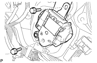
Remove the 2 bolts and rear seat outer belt assembly.
-