AIR CONDITIONING SYSTEM SYSTEM DESCRIPTION

-
GENERAL
-
The air conditioning system has the following controls.
Control Outline Neural Network Control This control is capable of performing complex control by artificially simulating the information processing method of the nervous system of living organisms in order to establish a complex input/output relationship similar to that of a human brain. Automatic Recirculation Control*1 Automatically changes the air inlet mode to the fresh air or recirculation air mode according to the level of harmful elements in the outside air, cabin temperature, and outside temperature. Outlet Air Temperature Control Based on the temperature set by the temperature control dial, the neural network control calculates outlet air temperature based on input signals from various sensors. Left and Right Independent Control The temperature settings for the driver and front passenger are controlled independently in order to provide separate vehicle interior temperatures for the right and left sides of the vehicle. Thus, air conditioning that accommodates the occupants preferences has been realized. Blower Control Controls the blower motor in accordance with the airflow volume that has been calculated by the neural network control based on the input signals from various sensors. Air Outlet Control Automatically switches the air outlets in accordance with the outlet mode that has been calculated by the neural network control. In accordance with the engine coolant temperature, ambient air temperature, amount of sunlight, required blower, outlet temperature and vehicle speed conditions, this control automatically switches the blower outlet to foot and defroster mode to prevent the windows from becoming fogged up when the ambient air temperature is low. Air Inlet Control Automatically controls the air inlet control damper to help achieve the calculated outlet air temperature that is required. Drives the air inlet control servo motor according to the operation of the air inlet control switch and moves the dampers to the fresh or recirculation position. Electric Inverter Compressor Control The A/C amplifier calculates the target speed of the compressor based on the target evaporator temperature (which is calculated by the room temperature sensor, outside temperature sensor, and the solar sensor) and the actual evaporator temperature that is detected by the evaporator temperature sensor in order to control the compressor speed. The A/C amplifier calculates the target evaporator temperature, which includes corrections based on the room temperature sensor, outside temperature sensor, the solar sensor, and evaporator temperature sensor. Accordingly, the A/C amplifier controls the compressor speed to an extent that would not inhibit the proper cooling performance or defogging performance. Defroster Control Defroster control logic is used to improve defroster performance. Rear Defogger Control When the power switch is on (IG) and the rear defogger switch is pushed, the system is activated to keep the defogger heater on for approx. 15 minutes. However, the operating time of the rear defogger can be extended up to approx. 60 minutes when both of the following requirements are met:
-
Ambient Temperature: 0°C (32°F) or less
-
Vehicle Speed: 37.3 mph (60 km/h) or more
Electric Water Pump Control When the blower motor is on and the engine has been stopped by the hybrid vehicle control system control, the A/C amplifier turns on the electric water pump in accordance with the judgment of the air mix damper opening. Memory Call Control Memorizes the last air conditioning settings when the power switch is turned from on (IG) to off in accordance with the ID code of the key that is used to operate the vehicle. The key-linked memory call control then recalls the settings if the key is used when the power switch is turned on (IG). This function operates when both of the following conditions are met:
-
Inside of the outside door handle is touched or the driver door is unlocked using the unlock button, and then the driver door is opened.
-
Power switch is turned on (IG).
Diagnosis A Diagnostic Trouble Code (DTC) is stored in the memory when the air conditioning amplifier detects a problem with the air conditioning system.
-
*1: w/ Navigation System
-
-
-
NEURAL NETWORK CONTROL
-
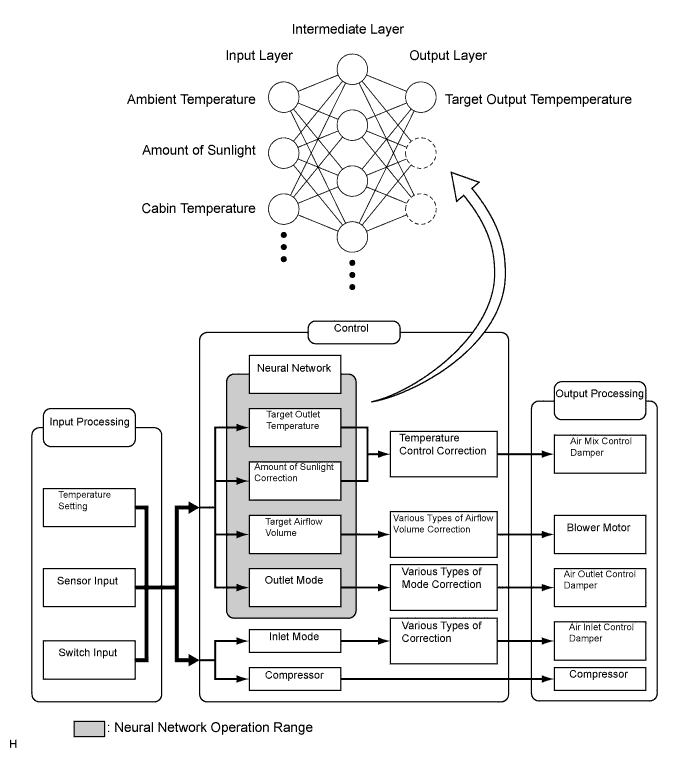
In the previous automatic air conditioning systems, the A/C amplifier determined the required outlet air temperature and blower air volume in accordance with the calculation formula that has been obtained based on information received from the sensors.
However, because the senses of a person are rather complex, a given temperature is sensed differently, depending on the environment in which the person is situated. For example, a given amount of solar radiation can feel comfortably warm in a cold climate, or extremely uncomfortable in a hot climate. Therefore, as a technique for effecting a higher level of control, a neural network has been adopted in the automatic air conditioning system. With this technique, the data that has been collected under varying environmental conditions is stored in the A/C amplifier. The A/C amplifier can then effect control to provide enhanced air conditioning comfort.
-
The neural network control consists of neurons in the input layer, intermediate layer and output layer. The input layer neurons process the input data of the outside temperature, the amount of sunlight and the room temperature based on the outputs of the switches and sensors, and output them to the intermediate layer neurons. Based on this data, the intermediate layer neurons adjust the strength of the links among the neurons. The sum of these is then calculated by the output layer neurons in the form of the required outlet temperature, solar correction, target airflow volume and outlet mode control volume. Accordingly, the A/C amplifier controls the servo motors and blower motor in accordance with the control volumes that have been calculated by the neural network control.
-
-
MODE POSITION AND DAMPER OPERATION
-
Mode Position and Damper Operation
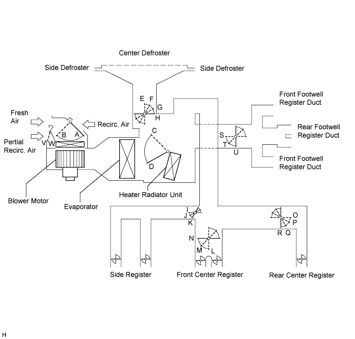
Functions of Main Dampers Control Damper Operation Position Damper Position Operation Air Inlet Control Damper FRESH A Allows fresh air to enter. RECIRCULATION B Causes internal air to recirculate. Air Mix Control Damper MAX COLD to MAX HOT Temperature Setting C - D Varies the mixture ratio of warm air and cool air in order to regulate the temperature continuously between hot and cold. Air Outlet Control Damper DEF

E, K, N, R, U Defrosts the windshield through the center defroster, side defrosters and side registers. FOOT/DEF

F, K, N, Q, S Defrosts the windshield through the center defroster, side defrosters and side registers while air is also blown out from the front and rear footwell register ducts. FOOT

G, K, N, Q, S Air blows out of the front and rear footwell register ducts, and side registers. In addition, air blows out slightly from the center defroster and side defrosters. BI-LEVEL

H, J, M, P, T Air blows out of the front center register, rear center register, side registers and front and rear footwell register ducts. FACE

H, I, L, O, U Air blows out of the front center register, rear center register and side registers. Partial Recirculated Door FRESH V - W Recirculates 15% of the interior air when the air conditioning is in fresh mode and the vehicle is driven at low speed with the blower motor at maximum.
-
-
AIR OUTLETS AND AIRFLOW VOLUME
-
Air Outlets and Airflow Volume
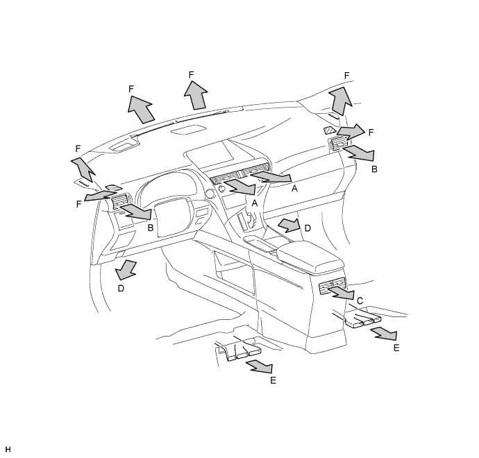
Indication Mode FACE FOOT DEF CTR SIDE RR FR RR F A B C D E FACE 

B/L 
FOOT 
F/D DEF The size of each circle ○ indicates the ratio of airflow volume.
-
-
AUTOMATIC RECIRCULATION CONTROL (w/ Navigation System)
-
When the automatic recirculation control is operating, the A/C amplifier automatically changes the air inlet mode to the fresh air or recirculate air mode based on signals from the smog ventilation sensor, ambient temperature and room temperature sensors when the AUTO air inlet mode is selected.
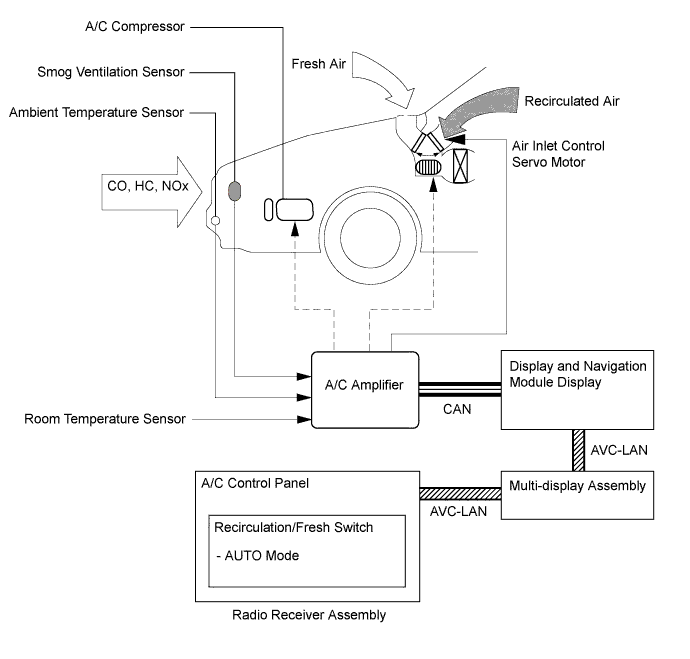
-
The A/C amplifier detects harmful elements (CO, HC, and NOx) based on a smog ventilation sensor signal and automatically switches the air inlet mode to the recirculate air mode to prevent such harmful elements from entering the cabin.
-
The A/C amplifier detects cabin temperature based on a room temperature sensor signal and automatically switches the air inlet mode to the recirculate air mode to prevent the cabin temperature from becoming too high.
-
The A/C amplifier detects the outside temperature based on an ambient temperature sensor signal and automatically switches the air inlet mode to the fresh air mode to prevent the windshield from fogging up.
Note
The smog ventilation sensor cannot detect elements such as the smoke from a bonfire or factory exhaust, foul or animal odors, and dirt or dust particles. Therefore, the air inlet mode is not switched automatically in accordance with those elements.
-
-
-
MEMORY CALL CONTROL
-
Memory call control memorizes the air conditioning system settings together with the ID code of the key that is being used.
-
When a key with memory is used to unlock the door, while the driver door is opened and the power switch is turned on (IG), the memorized air conditioning system settings will be recalled.
-
The certification ECU (smart key ECU) will recognize the key during the unlock operation by reading the registered ID code.
-
Using this control, the air conditioning system setting preference that corresponds to each key can be memorized, enhancing usability.
-
The following air conditioning system settings can be memorized:
Setting Condition A/C Switch On or Off AUTO Switch On or Off Temperature Setting Driver Side LO, 16 to 30°C (61 to 86°F) or HI Front Passenger Side LO, 16 to 30°C (61 to 86°F) or HI Blower Fan Speed Level 1 to 7 Air Inlet Mode Fresh or Recirculate Air Outlet Mode Face, Bi-Level, Foot, Foot/Defroster or Defroster DUAL Switch On or Off Tech Tips
Memory call control can be cancelled or re-enabled using the intelligent tester. When a new key is added, the key ID code registration is necessary Click here.
-
-
A/C COMPRESSOR
-
General
Tech Tips
In order to ensure the proper insulation of the internal high-voltage portion of the compressor and the compressor housing, this vehicle has adopted a compressor oil (ND11) with a high level of insulation performance. Therefore, never use a compressor oil other than the ND11 type compressor oil or its equivalent.
-
Along with the installation of the hybrid unit on this vehicle, an electric inverter compressor that is driven by a motor is used. The basic construction and operation of this compressor are the same as the ordinary scroll compressor, except that it is driven by an electric motor.
-
The Air Conditioning (A/C) inverter is integrated with the compressor.
-
The electric motor is actuated by 3-phase alternating current (244.8 V) supplied by the A/C inverter. As a result, the air conditioning control system on this vehicle is actuated without depending on the operation of the engine, thus realizing a comfortable air conditioning system and low fuel consumption.
-
Due to the use of an electric inverter compressor, the compressor speed can be controlled at the required speed calculated by the A/C amplifier. Thus, the cooling and dehumidification performance and power consumption have been optimized.
-
Low-moisture permeation hoses are used for the suction and discharge hoses at the compressor in order to minimize the entry of moisture into the refrigeration cycle.
-
The compressor uses high-voltage alternating current. If a short or open circuit occurs in the compressor wiring harness, the power management control ECU will cut off the A/C inverter circuit in order to stop the power supply to the compressor.
-
-
Compressor Speed Control
-
The A/C amplifier calculates the target compressor speed based on the target evaporator temperature (calculated from the room temperature sensor, outside temperature sensor, and solar sensor) and the actual evaporator temperature detected by the evaporator temperature sensor. Then, the A/C amplifier transmits the target speed to the power management control ECU. The power management control ECU controls the A/C inverter based on the target speed data in order to control the compressor to a speed that suits the operating condition of the air conditioning system.
-
The A/C amplifier calculates the target evaporator temperature, which includes corrections based on the room temperature sensor, outside temperature sensor, solar sensor, and evaporator temperature sensor. Accordingly, the A/C amplifier controls the compressor speed to an extent that does not inhibit the proper cooling performance or defogging performance. As a result, comfort and low fuel consumption can be realized.
-
-
-
ELECTRIC WATER PUMP
-
This vehicle uses an electric water pump for air conditioning. This provides a stable heater performance even if the engine is stopped because of a function of the hybrid control system.
-
This vehicle uses a new type of electrical water pump in which the water flow resistance has been reduced.
-
-
EVAPORATOR TEMPERATURE SENSOR
The evaporator temperature sensor detects the temperature of the cool air immediately through the evaporator in the form of resistance changes, and outputs it to the A/C amplifier.
-
BLOWER MOTOR
The blower motor has a built-in blower controller, and is controlled using duty control performed by the A/C amplifier.
-
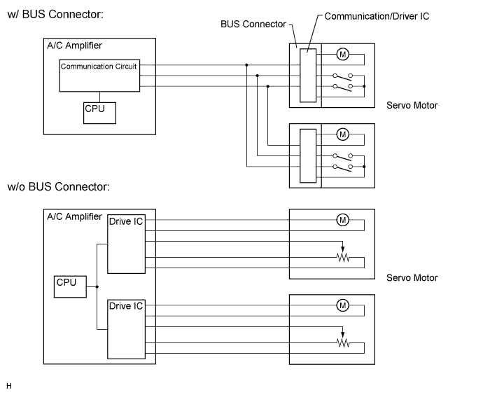
BUS CONNECTOR (AIR CONDITIONING HARNESS)
-
A BUS connector is used in the wire harness connection that connects the servo motor from the A/C amplifier.
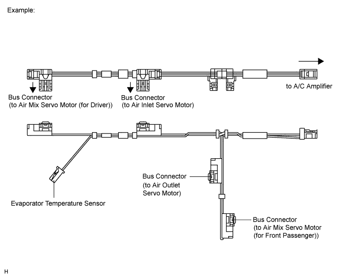
-
Each BUS connector has a built-in communication/driver IC which communicates with each servo motor connector, actuates the servo motor, and has a position detection function. This enables bus communication for the servo motor wire harness, for a more lightweight construction and a reduced number of wires.
-
-
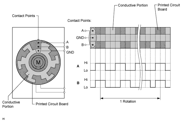
SERVO MOTOR
The pulse pattern type servo motor consists of a printed circuit board and a servo motor. The printed circuit board has three contact points, and can transmit two ON-OFF signals to the A/C amplifier based on the difference of the pulse phases. The BUS connector can detect the damper position and movement direction with these signals.
-
ROOM TEMPERATURE SENSOR (BUILT-IN HUMIDITY SENSOR)
-
The room temperature sensor detects the cabin temperature based on changes in the resistance of its built-in thermistor and sends a signal to the A/C amplifier.
-
A humidity sensor function has been added to the room temperature sensor. By enabling the detection of humidity in the vehicle interior, this function optimizes the amount of dehumidification effort during the operation of the A/C system. As a result, the power consumption of the compressor has been reduced and a comfortable level of humidity has been realized in the vehicle interior.
-
The humidity-sensing resistance film that is built into the humidity sensor absorbs and releases the humidity in the cabin. During the absorption and releasing processes, the humidity-sensing resistance film expands (during the absorption of humidity) and contracts (during drying). The clearance between the carbon particles in the humidity-sensing resistance film expands and contracts during absorption and drying, thus changing the resistance between the electrodes. The A/C amplifier determines the humidity in the cabin through the changes in the output voltage of the humidity sensor that are caused by the resistance between the electrodes.
-
-
AMBIENT TEMPERATURE SENSOR
The ambient temperature sensor detects the outside temperature based on changes in the resistance of its built-in thermistor and sends a signal to the A/C amplifier.
-
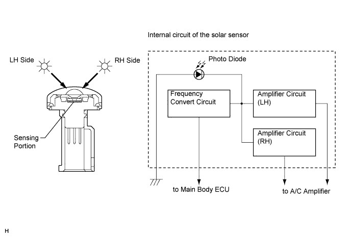
SOLAR SENSOR
-
The solar sensor consists of a photo diode, two amplifier circuits for the solar sensor, and frequency converter circuit for the light control sensor.
-
The solar sensor detects (in the form of changes in the current that flows through the built-in photo diode) the changes in the amount of sunlight from the LH and RH sides (2 directions) and outputs these sunlight strength signals to the A/C amplifier.
-
-
A/C PRESSURE SENSOR
The A/C pressure sensor detects the refrigerant pressure and outputs it to the A/C amplifier in the form of voltage changes.