CLIMATE CONTROL SEAT SYSTEM Climate Control Seat System does not Operate
DESCRIPTION
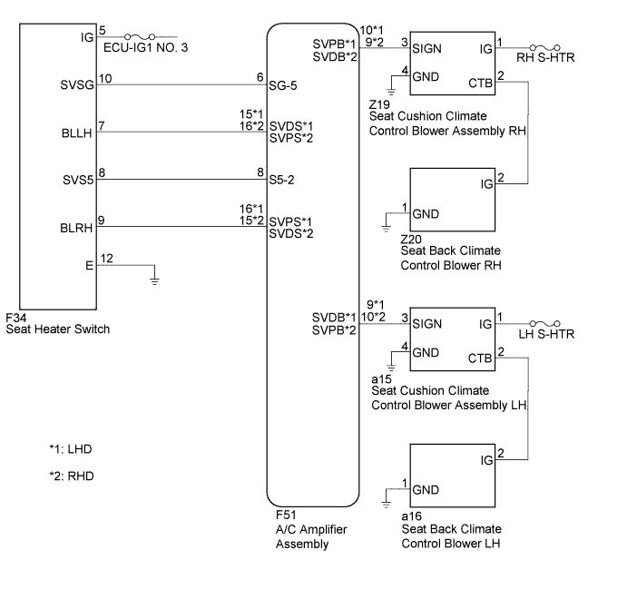
The A/C amplifier assembly receives seat heater switch position signals when the power switch is turned on (IG), and then transmits airflow amount signals to each seat climate blower.
WIRING DIAGRAM
INSPECTION PROCEDURE
PROCEDURE
-
SYSTEM CHECK
-
Check the climate control seat operation.
Result Result Proceed to Climate control seat does not operate (Front LH) A Climate control seat does not operate (Front RH) B Both climate control seats do not operate C
B 
SYSTEM CHECK Click here
C
INSPECT SEAT HEATER SWITCH Click here
A 
-
-
SYSTEM CHECK
-
Check the climate control operation again.
Result Result Proceed to Only seat back climate control blower LH does not operate A Both climate control blowers do not operate B
B
CHECK HARNESS AND CONNECTOR Click here
A
-
-
CHECK HARNESS AND CONNECTOR
-
Text in Illustration *1 Front view of wire harness connector
(to Seat Back Climate Control Blower LH)
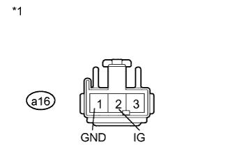
Disconnect the a16 connector.
-
Measure the voltage according to the value(s) in the table below.
Standard Voltage Tester Connection Condition Specified Condition a16-2 (IG) - a16-1 (GND) Power switch on (IG)
Blower switch ON (Vol: 1 to 3)
6.7 to 9.3 V
NG
CHECK HARNESS AND CONNECTOR Click here
OK 
REPLACE SEAT BACK CLIMATE CONTROL BLOWER LH Click here
-
-
CHECK HARNESS AND CONNECTOR
-

Text in Illustration *1 Front view of wire harness connector
(to Seat Cushion Climate Control Blower Assembly LH)
*2 Front view of wire harness connector
(to Seat Back Climate Control Blower LH)
Disconnect the a15 connector.
-
Measure the resistance according to the value(s) in the table below.
Standard Resistance Tester Connection Condition Specified Condition a16-2 (IG) - a15-2 (CTB) Always Below 1 Ω a16-2 (IG) - Body ground Always 10 kΩ or higher a16-1 (GND) - Body ground Always Below 1 Ω
NG 
REPAIR OR REPLACE HARNESS OR CONNECTOR
OK
REPLACE SEAT CUSHION CLIMATE CONTROL BLOWER ASSEMBLY LH Click here
-
-
CHECK HARNESS AND CONNECTOR
-

Text in Illustration *1 Front view of wire harness connector
(to Seat Cushion Climate Control Blower Assembly LH)
Disconnect the a15 connector.
-
Measure the voltage and resistance according to the value(s) in the table below.
Standard Voltage and Resistance Tester Connection Condition Specified Condition a15-1 (IG) - Body ground Power switch on (IG) 11 to 14 V a15-4 (GND) - Body ground Always Below 1 Ω
NG
REPAIR OR REPLACE HARNESS OR CONNECTOR
OK
-
-
CHECK AIR CONDITIONING AMPLIFIER ASSEMBLY
-
Text in Illustration *1 Component with harness connected
(Seat Cushion Climate Control Blower Assembly LH)
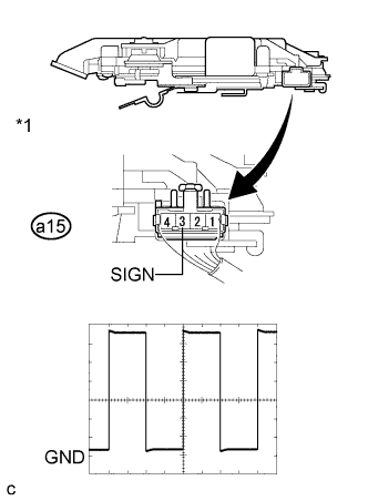
Reconnect the a15 connector.
-
Check the input signal waveform.
-
Connect the oscilloscope to terminal 3 and body ground with the seat cushion climate control blower assembly LH connector still connected.
-
Check the signal waveform according to the condition(s) in the table below.
Terminal No. a15-3 (SIGN) - Body ground Tool Setting 2 V/DIV., 500 μsec./DIV. Vehicle Condition Power switch on (IG), seat hater switch ON
-
NG
CHECK HARNESS AND CONNECTOR Click here
OK
REPLACE SEAT CUSHION CLIMATE CONTROL BLOWER ASSEMBLY LH Click here
-
-
CHECK HARNESS AND CONNECTOR
-
for LHD
-
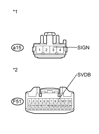
Text in Illustration *1 Front view of wire harness connector
(to Seat Cushion Climate Control Blower Assembly LH)
*2 Front view of wire harness connector
(to A/C amplifier Assembly)
Disconnect the a15 and F51 connectors.
-
Measure the resistance according to the value(s) in the table below.
Standard Resistance Tester Connection Condition Specified Condition a15-3 (SIGN) - F51-9 (SVDB) Always Below 1 Ω a15-3 (SIGN) - Body ground Always 10 kΩ or higher
-
-
for RHD
-
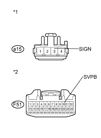
Text in Illustration *1 Front view of wire harness connector
(to Seat Cushion Climate Control Blower Assembly LH)
*2 Front view of wire harness connector
(to A/C amplifier Assembly)
Disconnect the a15 and F51 connectors.
-
Measure the resistance according to the value(s) in the table below.
Standard Resistance Tester Connection Condition Specified Condition a15-3 (SIGN) - F51-10 (SVPB) Always Below 1 Ω a15-3 (SIGN) - Body ground Always 10 kΩ or higher
-
NG
REPAIR OR REPLACE HARNESS OR CONNECTOR
OK
-
-
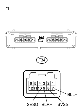
INSPECT SEAT HEATER SWITCH
-
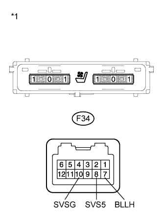
Text in Illustration *1 Component without harness connected
(Seat Heater Switch)
Remove the seat heater switch Click here.
-
Measure the resistance according to the value(s) in the table below.
Standard Resistance Tester Connection Condition Specified Condition F34-8 (SVS5) - F34-10 (SVSG) Always 1.54 to 2.86 kΩ F34-7 (BLLH) - F34-10 (SVSG) Blower switch OFF 1.54 to 2.86 kΩ F34-7 (BLLH) - F34-10 (SVSG) Blower switch ON (Vol: 3) Below 1 to 100 Ω
NG
REPLACE SEAT HEATER SWITCH Click here
OK
-
-
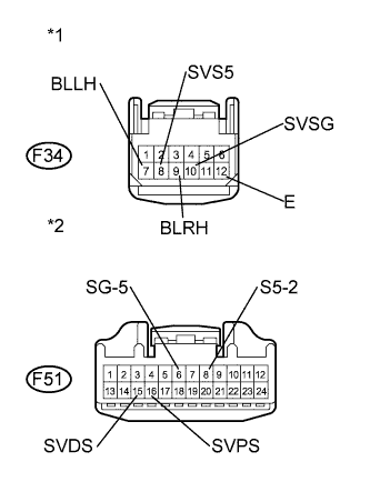
CHECK HARNESS AND CONNECTOR
-
for LHD
-
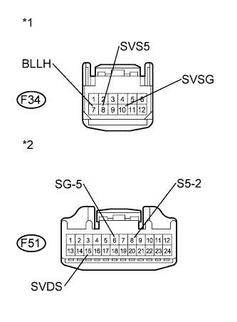
Text in Illustration *1 Front view of wire harness connector
(to Seat Heater Switch)
*2 Front view of wire harness connector
(to A/C Amplifier Assembly)
Measure the resistance according to the value(s) in the table below.
Standard Resistance Tester Connection Condition Specified Condition F34-7 (BLLH) - F51-15 (SVDS) Always Below 1 Ω F34-8 (SVS5) - F51-8 (S5-2) Always Below 1 Ω F34-10 (SVSG) - F51-6 (SG-5) Always Below 1 Ω F34-7 (BLLH) - Body ground Always 10 kΩ or higher F34-8 (SVS5) - Body ground Always 10 kΩ or higher F34-10 (SVSG) - Body ground Always 10 kΩ or higher
-
-
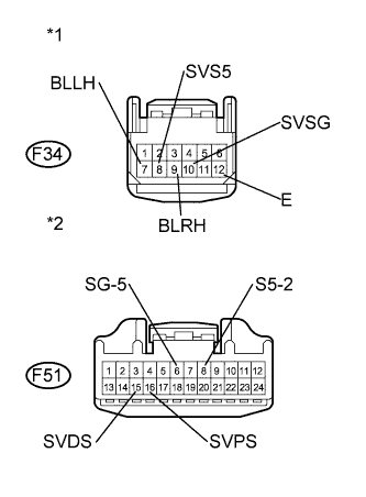
for RHD
-
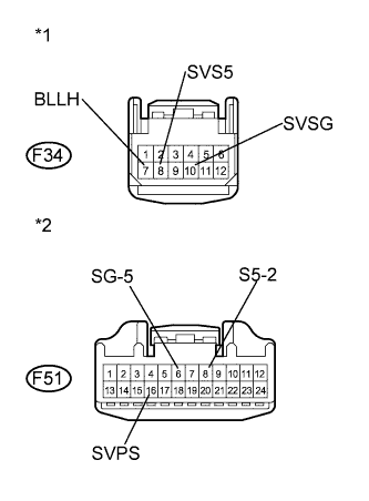
Text in Illustration *1 Front view of wire harness connector
(to Seat Heater Switch)
*2 Front view of wire harness connector
(to A/C Amplifier Assembly)
Measure the resistance according to the value(s) in the table below.
Standard Resistance Tester Connection Condition Specified Condition F34-7 (BLLH) - F51-16 (SVPS) Always Below 1 Ω F34-8 (SVS5) - F51-8 (S5-2) Always Below 1 Ω F34-10 (SVSG) - F51-6 (SG-5) Always Below 1 Ω F34-7 (BLLH) - Body ground Always 10 kΩ or higher F34-8 (SVS5) - Body ground Always 10 kΩ or higher F34-10 (SVSG) - Body ground Always 10 kΩ or higher
-
NG
REPAIR OR REPLACE HARNESS OR CONNECTOR
OK
REPLACE AIR CONDITIONING AMPLIFIER ASSEMBLY Click here
-
-
SYSTEM CHECK
-
Check the climate control operation again.
Result Result Proceed to Only seat back climate control blower RH does not operate A Both climate control blowerS do not operate B
B
CHECK HARNESS AND CONNECTOR Click here
A
-
-
CHECK HARNESS AND CONNECTOR
-
Disconnect the Z20 connector.
-
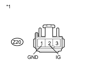
Text in Illustration *1 Front view of wire harness connector
(to Seat Back Climate Control Blower RH)
Measure the voltage according to the value(s) in the table below.
Standard Voltage Tester Connection Condition Specified Condition Z20-2 (IG) - Z20-1 (GND) Power switch on (IG)
Blower switch ON (Vol: 1 to 3)
6.7 to 9.3 V
NG
CHECK HARNESS AND CONNECTOR Click here
OK
REPLACE SEAT BACK CLIMATE CONTROL BLOWER RH Click here
-
-
CHECK HARNESS AND CONNECTOR
-
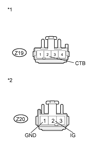
Text in Illustration *1 Front view of wire harness connector
(to Seat Cushion Climate Control Blower Assembly RH)
*2 Front view of wire harness connector
(to Seat Back Climate Control Blower RH)
Disconnect the Z19 connector.
-
Measure the resistance according to the value(s) in the table below.
Standard Resistance Tester Connection Condition Specified Condition Z20-2 (IG) - Z19-2 (CTB) Always Below 1 Ω Z20-2 (IG) - Body ground Always 10 kΩ or higher Z20-1 (GND) - Body ground Always Below 1 Ω
NG
REPAIR OR REPLACE HARNESS OR CONNECTOR
OK
REPLACE SEAT CUSHION CLIMATE CONTROL BLOWER ASSEMBLY RH Click here
-
-
CHECK HARNESS AND CONNECTOR
-
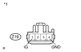
Text in Illustration *1 Front view of wire harness connector
(to Seat Cushion Climate Control Blower Assembly RH)
Disconnect the Z19 connector.
-
Measure the voltage and resistance according to the value(s) in the table below.
Standard Voltage and Resistance Tester Connection Condition Specified Condition Z19-1 (IG) - Body ground Power switch on (IG) 11 to 14 V Z19-4 (GND) - Body ground Always Below 1 Ω
NG
REPAIR OR REPLACE HARNESS OR CONNECTOR
OK
-
-
CHECK AIR CONDITIONING AMPLIFIER ASSEMBLY
-
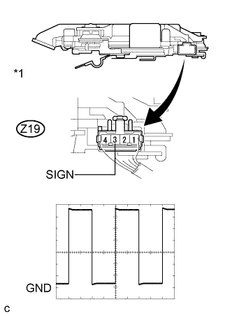
Text in Illustration *1 Component with harness connected
(Seat Cushion Climate Control Blower Assembly RH)
Reconnect the Z19 connector.
-
Check the input signal waveform.
-
Connect the oscilloscope to terminal 3 and body ground with the climate control blower assembly RH connector still connected.
-
Check the signal waveform according to the condition(s) in the table below.
Terminal No. Z19-3 (SIGN) - Body ground Tool Setting 2 V/DIV., 500 μsec./DIV. Vehicle Condition Power switch on (IG), seat heater switch ON
-
NG
CHECK HARNESS AND CONNECTOR Click here
OK
REPLACE SEAT CUSHION CLIMATE CONTROL BLOWER ASSEMBLY RH Click here
-
-
CHECK HARNESS AND CONNECTOR
-
for LHD
-

Text in Illustration *1 Front view of wire harness connector
(to Seat Cushion Climate Control Blower Assembly RH)
*2 Front view or wire harness connector
(to A/C Amplifier Assembly)
Disconnect the Z19 and F51 connectors.
-
Measure the resistance according to the value(s) in the table below.
Standard Resistance Tester Connection Condition Specified Condition Z19-3 (SIGN) - F51-10 (SVPB) Always Below 1 Ω Z19-3 (SIGN) - Body ground Always 10 kΩ or higher
-
-
for RHD
-
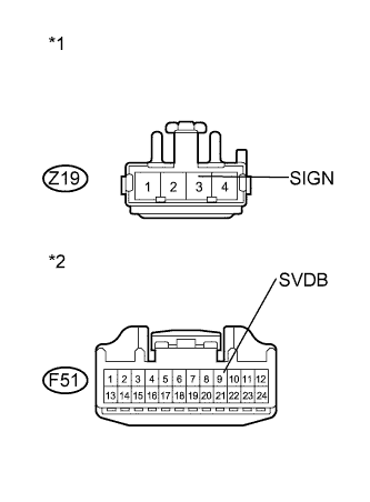
Text in Illustration *1 Front view of wire harness connector
(to Seat Cushion Climate Control Blower Assembly RH)
*2 Front view or wire harness connector
(to A/C Amplifier Assembly)
Disconnect the Z19 and F51 connectors.
-
Measure the resistance according to the value(s) in the table below.
Standard Resistance Tester Connection Condition Specified Condition Z19-3 (SIGN) - F51-9 (SVDB) Always Below 1 Ω Z19-3 (SIGN) - Body ground Always 10 kΩ or higher
-
NG
REPAIR OR REPLACE HARNESS OR CONNECTOR
OK
-
-
INSPECT SEAT HEATER SWITCH
-
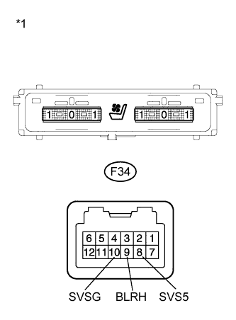
Text in Illustration *1 Component without harness connected
(Seat Heater Switch)
Remove the seat heater switch Click here.
-
Measure the resistance according to the value(s) in the table below.
Standard Resistance Tester Connection Condition Specified Condition F34-8 (SVS5) - F34-10 (SVSG) Always 1.54 to 2.86 kΩ F34-9 (BLRH) - F34-10 (SVSG) Blower switch OFF 1.54 to 2.86 kΩ F34-9 (BLRH) - F34-10 (SVSG) Blower switch ON (Vol: 3) Below 1 to 100 Ω
NG
REPLACE SEAT HEATER SWITCH Click here
OK
-
-
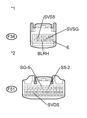
CHECK HARNESS AND CONNECTOR
-
for LHD
-
Text in Illustration *1 Front view of wire harness connector
(to Seat Heater Switch)
*2 Front view of wire harness connector
(to A/C Amplifier Assembly)
Measure the resistance according to the value(s) in the table below.
Standard Resistance Tester Connection Condition Specified Condition F34-9 (BLRH) - F51-16 (SVPS) Always Below 1 Ω F34-8 (SVS5) - F51-8 (S5-2) Always Below 1 Ω F34-10 (SVSG) - F51-6 (SG-5) Always Below 1 Ω F34-12 (E) - Body ground Always Below 1 Ω F34-9 (BLRH) - Body ground Always 10 kΩ or higher F34-8 (SVS5) - Body ground Always 10 kΩ or higher F34-10 (SVSG) - Body ground Always 10 kΩ or higher
-
-
for RHD
-
Text in Illustration *1 Front view of wire harness connector
(to Seat Heater Switch)
*2 Front view of wire harness connector
(to A/C Amplifier Assembly)
Measure the resistance according to the value(s) in the table below.
Standard Resistance Tester Connection Condition Specified Condition F34-9 (BLRH) - F51-15 (SVDS) Always Below 1 Ω F34-8 (SVS5) - F51-8 (S5-2) Always Below 1 Ω F34-10 (SVSG) - F51-6 (SG-5) Always Below 1 Ω F34-12 (E) - Body ground Always Below 1 Ω F34-9 (BLRH) - Body ground Always 10 kΩ or higher F34-8 (SVS5) - Body ground Always 10 kΩ or higher F34-10 (SVSG) - Body ground Always 10 kΩ or higher
-
NG
REPAIR OR REPLACE HARNESS OR CONNECTOR
OK
REPLACE AIR CONDITIONING AMPLIFIER ASSEMBLY Click here
-
-
INSPECT SEAT HEATER SWITCH
-
Text in Illustration *1 Component without harness connected
(Seat Heater Switch)
Remove the seat heater switch Click here.
-
Measure the resistance according to the value(s) in the table below.
Standard Resistance Tester Connection Condition Specified Condition F34-8 (SVS5) - F34-10 (SVSG) Always 1.54 to 2.86 kΩ F34-7 (BLLH) - F34-10 (SVSG) Blower switch OFF 1.54 to 2.86 kΩ F34-7 (BLLH) - F34-10 (SVSG) Blower switch ON (Vol: 3) Below 1 to 100 Ω F34-9 (BLRH) - F34-10 (SVSG) Blower switch OFF 1.54 to 2.86 kΩ F34-9 (BLRH) - F34-10 (SVSG) Blower switch ON (Vol: 3) Below 1 to 100 Ω
NG
REPLACE SEAT HEATER SWITCH Click here
OK
-
-
CHECK HARNESS AND CONNECTOR
-
for LHD
-
Text in Illustration *1 Front view of wire harness connector
(to Seat Heater Switch)
*2 Front view of wire harness connector
(to A/C Amplifier Assembly)
Disconnect the F51 connector.
-
Measure the resistance according to the value(s) in the table below.
Standard Resistance Tester Connection Condition Specified Condition F34-7 (BLLH) - F51-15 (SVDS) Always Below 1 Ω F34-8 (SVS5) - F51-8 (S5-2) Always Below 1 Ω F34-9 (BLRH) - F51-16 (SVPS) Always Below 1 Ω F34-10 (SVSG) - F51-6 (SG-5) Always Below 1 Ω F34-7 (BLLH) - Body ground Always 10 kΩ or higher F34-8 (SVS5) - Body ground Always 10 kΩ or higher F34-9 (BLRH) - Body ground Always 10 kΩ or higher F34-10 (SVSG) - Body ground Always 10 kΩ or higher
-
-
for RHD
-
Text in Illustration *1 Front view of wire harness connector
(to Seat Heater Switch)
*2 Front view of wire harness connector
(to A/C Amplifier Assembly)
Disconnect the F51 connector.
-
Measure the resistance according to the value(s) in the table below.
Standard Resistance Tester Connection Condition Specified Condition F34-7 (BLLH) - F51-16 (SVPS) Always Below 1 Ω F34-8 (SVS5) - F51-8 (S5-2) Always Below 1 Ω F34-9 (BLRH) - F51-15 (SVDS) Always Below 1 Ω F34-10 (SVSG) - F51-6 (SG-5) Always Below 1 Ω F34-7 (BLLH) - Body ground Always 10 kΩ or higher F34-8 (SVS5) - Body ground Always 10 kΩ or higher F34-9 (BLRH) - Body ground Always 10 kΩ or higher F34-10 (SVSG) - Body ground Always 10 kΩ or higher
-
NG
REPAIR OR REPLACE HARNESS OR CONNECTOR
OK
REPLACE AIR CONDITIONING AMPLIFIER ASSEMBLY Click here
-